


PCAN-Diag 2 – Oscilloscope Function
61
Configuration of trigger to frame start, frame end, CAN errors,
CAN ID, or signal edges.
External measurement devices can be triggered using the BNC
connector
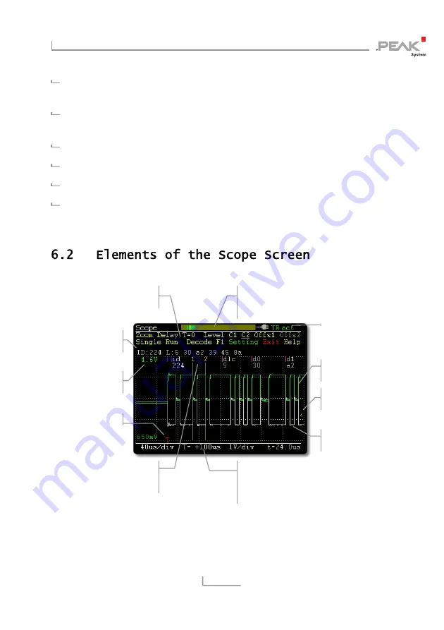
Depiction of raw CAN frames
Decoding of CAN frames from the recorded signal course
Current view can be saved as bitmap screenshot
Saving the recorded sample data as CSV file
Signal course measuring
channel 1 (green)
Signal course measuring
channel 2 (white)
Display of triggering
level for edge trigger
Measuring cursors C1 (yellow)
and C2 (orange) for time period
measurement
Position bar for overview of the
sample buffer (current view, trigger,
measuring cursors)
Actions (see the following
manual sections)
CAN data decoded from
the signal course
Displayed voltage range
(upper boundary)
us/div: grid resolution time axis (hor.)
T=: view
position
V/div: grid resolution voltage axis (vert.)
t=:
time period from measurement C1/C2
Trigger position
Summary of Contents for IPEH-002069-V2
Page 1: ...PCAN Diag 2 Handheld Device for CAN Bus Diagnostics User Manual V2 3 1 ...
Page 6: ...PCAN Diag 2 User Manual 6 11 4 PCAN Diag Files on the Internal Memory Card 93 ...
Page 43: ...PCAN Diag 2 CAN Traffic 43 Data display after assigning the symbol file in the PCAN Diag ...
Page 98: ...PCAN Diag 2 Appendix 98 ...