PCS Electronics CyberMax Series Manual Download Page 29

Brought to you by PCS Electronics, www.pcs-electronics.com 


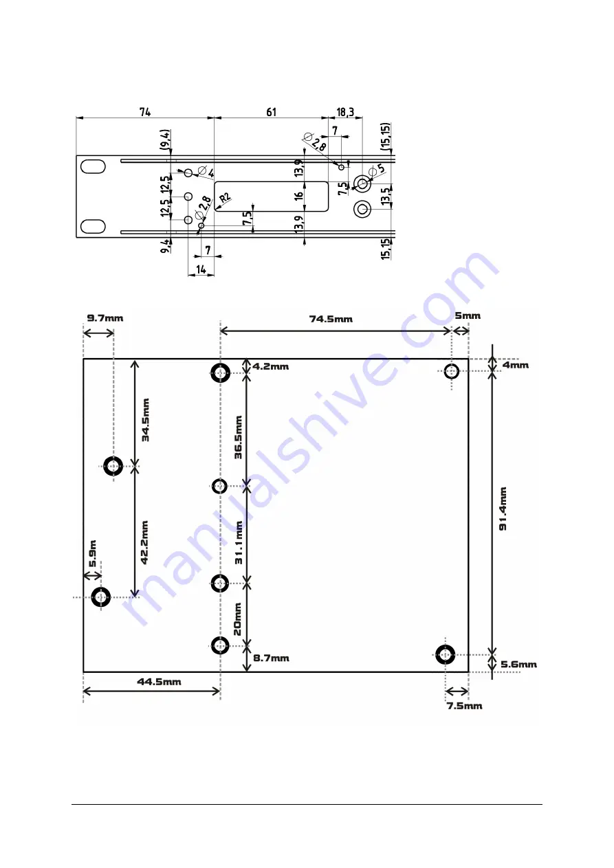
RF and LCD module drill template/cutout 

LCD control module is pretty simple and self-explanatory, but let us have a quick look;  


Fig. 33: LCD module cutout and holes, all measurements in mm 


Fig. 34: Drill template for main board 

Summary of Contents for CyberMax Series

Page 1: ...Brought to you by PCS Electronics www pcs electronics com CyberMax series amplifiers And Universal Amplifier control Board v4 0 Manual ...

Page 2: ...t power of the amplifier Ensure amplifier supply voltage does not exceed amplifier s specifications It is recommended that you use reduced supply voltage for initial tests and first power up Never operate any amplifier without a properly tuned antenna or dummy load attached Mains voltage is lethal Whenever handling mains voltage be very careful and observe safety regulations Study local regulation...

Page 3: ...ks about 5 Coaxial cable 5 Connectors 5 Mains power supply and mains power cable 5 Signal exciter for your amplifier 5 Wiring everything together 6 Wiring things up and first power up 6 Menu system and settings 7 LCD control module two types 7 LCD control module menu system 7 Changing output power 7 AUTO FAN TEMP 7 VIEW SELECT 8 LCD CONTRAST 8 ALARMS UP DWN 8 CURRENT ALARM 8 TEMP ALARM 9 SWR ALARM...

Page 4: ...endix A IO board and PC remote control 15 Software installation 15 Using existing COM port 16 Installing USB driver only for USB IO board 16 Configuring USB driver 16 Setting up com port in CyberMaxFM program 17 Appendix B Setting up remote control via Ethernet 18 Software installation 18 Appendix C Universal amplifier control board layout 21 Main board layout 21 LCD module layout 23 RF and LCD mo...

Page 5: ...rought to you by PCS Electronics www pcs electronics com Warranty and servicing 30 Legal info 30 Limitation of liability 30 Also available from www pcs electronics com 30 Revisions and errata 31 Index 32 ...

Page 6: ...drive power and temperature read out Remote monitoring available for Windows Technical specifications Output RF connector N female 0 900W 7 16 900W 3000W Input RF connector N female Drive power Depends on the model check our website for specifications often set according to customer s requirement Output power power Depends on the model check our website for specifications often set according to cu...

Page 7: ... in case of SWR TEMP or other error There can be several of these depending on the model 5 Power switch in the middle of the panel is actually a standby switch To really fully disconnect the unit from mains power use the main switch at the back 6 Monitor output at the front provides a small sample of the transmitter signal this can be used to attach frequency counter modulation index monitor spect...

Page 8: ...C connectors for MPXin MPXout and 19KHz pilot Only when used as FM transmitter 6 RS232 USB for remote control 7 Audio inputs RCA jacks for left and right channel Only when used as FM transmitter 8 STEREO mode indicator Only when used as FM transmitter 9 10 Balanced audio inputs left and right channel XLR Canon Only when used as FM transmitter 11 Ethernet optional port for remote control 12 Not sho...

Page 9: ... full power and a bit of the antenna came off in your hand the VSWR could be so bad as to blow the final transistor For the same reason check the DC continuity of the antenna with an ohmmeter before plugging it in to be sure it s what it s meant to be either a short circuit or an open one depending on the antenna type For instructions regarding construction of antennas please see our website http ...

Page 10: ...cast and networking systems Most coaxial cables have a characteristic impedance of either 50 or 75 ohms The RF industry uses standard type names for coaxial cables The U S military uses the RG or RG U format probably for radio grade universal but other interpretations exist The common RG 58 from Radio Shack is NOT the best you can do and can eat a lot of your effective power out Use it only for sh...

Page 11: ...wer up yet Connect the jumper cable between amplifier and signal generator exciter Now power up the amplifier and wait for it to boot up It will wait in stand by until RF signal appears Set desired power in percentage with the big rotary button Maybe 25 for a start Power up the exciter and make sure it is set correctly set expected drive power If necessary disengage the stand by mode flip the swit...

Page 12: ...ntrol module menu system The rotary button is used to change parameter values In normal mode the LCD simply shows the output power and other parameters depending on view you select Menu system can be entered by repeatedly pressing this rotary button which brings up the following menus AUTO FAN TEMP VIEW SELECT LCD CONTRAST ALARMS UP DWN CURRENT ALRM TEMP ALARM SWR ALARM U AMP ALARM DRIVE LIMIT OUT...

Page 13: ...ve to wait a few seconds for the view to change Auto scroll is a recommended setting Fig 5 Setting mode to stereo LCD CONTRAST Select for the best visibility Contrast is slightly affected by ambient temperature and you can adapt it to your needs here Fig 6 Changing contrast ALARMS UP DWN This is a gateway entrance into to a group of settings This was done to group similar settings into sub categor...

Page 14: ...IGIAMP Fig 9 Temperature alarm SWR ALARM You can set the sensitivity of software driven SWR alarm here Fig 10 Temperature alarm U AMP ALARM You can set the sensitivity of amplifier supply voltage alarm here We recommend you set these according to your amplifier Usually this is around 50V This alarm only works if you use PCS LPF 6000 7000 filters with voltage sensor Fig 11 Amplifier voltage alarm D...

Page 15: ...CD module firmware version Fig 14 Firmware version PASSWORD Rotary display version of the display also lets you lock the display with a password For this to work you have to install LOCK jumper to pins marked LOCK on the LCD display Anytime you want to do something with the display you will have to enter password first The LCD stays unlocked for about a minute after that Once you enter this sub me...

Page 16: ...tion via serial COM port or USB port are described in Appendix I COM PORT SETUP Select correct COM port here Fig 15 COM port setup The selected COM port must match the COM port detected under Device Manager To open device manager enter Device Manager into search box in Windows than click Device Manager Fig 16 COM port in device manager must match the one in CyberMaxAmp program Chapter 6 ...

Page 17: ...y at start checkbox to start the program minimized in system tray Auto read status Check this box to activate automatic continuous hardware status reading RF amplifier status Shows various currents and voltages inside the amplifier Alarm indicator buttons SWR ALARM PSU T ALARM and others These light up when an alarm is triggered in the amplifier Must be connected to amplifier and auto read enabled...

Page 18: ... a fuse SWR and TEMP protection Fuse is the first thing to check Make sure your coaxial cable leading to the transmitter or antenna is not shorted or open Next check the troubleshooting table on the next page If you have problems you cannot solve yourself please see our website for contact information and support resources in our forum Fig 18 So do you think you can handle it We think you sure can...

Page 19: ...ybe your unit is over heating or your antenna SWR may be way off Let the unit cool off and ensure proper cooling in the future Perhaps you adjusted TEMP ALARM or another alarm too low set it slightly higher 4 Exciter or driver may be too weak 5 Power limit may be set too low it is shown at power up time LCD display keeps showing TEMP SWR error warning 1 Unit is probably over heating or your antenn...

Page 20: ...orward and should only take a few minutes Wait for the installation to complete and click Finish when done Follow instructions on the Fig 19 Setup is about to start Fig 20 CyberMaxAMP remote control software As you can see this program lets you control all the parameters of your FM transmitter including RDS parameters It also lets you read all of the available information such as output power temp...

Page 21: ...rts Installing USB driver only for USB IO board Download the USB COM port driver you can find it here http www pcs electronics com phpBB2 viewtopic php t 2505 Now run the setup file Wait for the following screen or very similar to appear and select the installation directory best left alone at default location Click Install and wait for the installation to finish Fig 21 Installing USB driver Confi...

Page 22: ...ll open You can set COM port manually or you can use the Autoscan feature Make sure to set FM Transmitter type correctly 4 0 for new versions of MAXPRO6000 series and make sure the exciter board is turned on A short guide for manual settings read above and make note of the used COM port If you are using USB it will usually be COM5 when using RS232 it will usually be COM1 or 2 You can use Communica...

Page 23: ... installation to complete and then start the program Connect the amplifier to your network via Ethernet cable The Ethernet adapter is setup to accept IP from your router s DHCP server It is possible to setup Ethernet adapter with fixed IP or to login directly to ADSL modem If you need MAC address of the Ethernet adapter open the cover of the unit and look at the Ethernet adapter the MAC address is...

Page 24: ...Brought to you by PCS Electronics www pcs electronics com Fig 26 Setting up Ethernet connection screen 2 Fig 27 Setting up Ethernet connection screen 3 ...

Page 25: ...Brought to you by PCS Electronics www pcs electronics com Fig 28 Setting up Ethernet connection screen 4 Fig 29 Setting up Ethernet connection overview ...

Page 26: ...Brought to you by PCS Electronics www pcs electronics com Appendix C Universal amplifier control board layout Main board layout Fig 30 Universal amplifier control board v4 0 Appendix C ...

Page 27: ...L J10 Stand by indicator LED M J8 Stand by switch N J7 VU meter header Connects to VUMAX 1 Shows output power and SWR on 2 of the 4 available LED bar graphs O P4 SWR meter adjustment P P3 PWR meter adjustment Q J3 PWR meter sensitivity adjustment install jumper R J5 Solder pads for external directional coupler power swr meter no need to connect when you use Digiamp pcs lpf 5000 or 6000 S J4 Bias d...

Page 28: ...tor LED This LED is activated when RF output stage is NOT active For example whenever if temperature protection is activated this LED illuminates and RF power is reduced Important This LED is also illuminated whenever you change frequency as the control unit turns RF power off until adjustments are finished and VCO is locked In such case this does not signal a problem with temperature or SWR 6 7 M...

Page 29: ...pcs electronics com RF and LCD module drill template cutout LCD control module is pretty simple and self explanatory but let us have a quick look Fig 33 LCD module cutout and holes all measurements in mm Fig 34 Drill template for main board ...

Page 30: ...is definitely not the best for FM radio and offers only limited range of reliable control Controlling ob bias point has its shortcomings as well it can also lead to instability and its range of control is also limited Controlling of supply voltage enables full control of power practically down to zero You may need to use it in tandem with controlling of drive power to prevent saturation when used ...

Page 31: ...ard v4 0 3 FM amplifier under control 4 LCD control module 5 TEMP sensor 10K NTC resistor 6 5000 or 6000 series filter from PCS Electronics 7 RF drive 8 On board 12V power from on board DCDC converter 2A max including 12V fan 9 Automatic 48V FAN 10 Automatic 12V FAN Table 6 Description of various blocks of the Universal Amplifier Board v4 0 ...

Page 32: ...ct header J11 F directly to this control voltage input In order for this to work you have to install the two jumpers J11 This mode of operation is called mode B Another thing to consider is that with some mains power supplies the output voltage rises proportionally with the control voltage and with other it is inversely proportionally to the control voltage You can compensate for this with J20 J I...

Page 33: ...ly voltage Measured Power and SWR lines ALC used only for exciters 5V and GND Standby switch J8 and LED J10 You can connect a switch with built in LED diode here Whenever you activate standby mode the supply voltage drops and bias disable is activated Makes it possible to quickly disable RF output BIAS DISABLE output Most pallets have bias control inputs this input is designed to shut off the pall...

Page 34: ...ww pcs electronics com frequency meter If you do not wish to use it draw a small sensor wire from the RF input of the control board to the RF input of the amp just couple it loosely via 1pF 10pF capacitor depending on used frequency band ...

Page 35: ...make sure you operate in accordance with local laws and or regulations Limitation of liability To the law in no event shall PCS Elektronik d o o or its suppliers be liable for any special incidental indirect or consequential damages whatsoever including without limitation damages for loss of business profits business interruption loss of business information or any other pecuniary loss arising out...

Page 36: ...you by PCS Electronics www pcs electronics com Revisions and errata V1 0 August 2020 Release version Please report any errors you see in this manual you will be helping us and many other users out there Thank you ...

Page 37: ...32 Index block diagram 7 LCD module layout 5 Lock Keys 5 Main board layout 3 menu system 11 module drill template 6 Technical specifications 2 Troubleshooting 14 ...

Reviews: