background image

©  PCE Instruments 

PCE Instruments contact information 

Spain 

PCE Ibérica S.L. 
Calle Mayor, 53 
02500 Tobarra (Albacete) 
España 
Tel. : +34 967 543 548 
Fax: +34 967 543 542 
[email protected] 
www.pce-instruments.com/
espanol 

Italy 

PCE Italia s.r.l. 
Via Pesciatina 878 / B-Interno 6 
55010 LOC. GRAGNANO  
CAPANNORI (LUCCA) 
Italia 
Telefono: +39 0583 975 114  
Fax: +39 0583 974 824  
[email protected] 
www.pce-instruments.com/
italiano 

Hong Kong 

PCE Instruments HK Ltd. 
Unit J, 21/F., COS Centre 
56 Tsun Yip Street 
Kwun Tong 
Kowloon, Hong Kong 
Tel: +852-301-84912 
[email protected] 
www.pce-instruments.cn 

Germany 

PCE Deutschland GmbH 
Im Langel 4 
D-59872 Meschede
Deutschland
Tel.: +49 (0) 2903 976 99 0
Fax: +49 (0) 2903 976 99 29
[email protected]
www.pce-instruments.com/
deutsch

United States of America 

PCE Americas Inc. 
711 Commerce Way suite 8 
Jupiter / Palm Beach 
33458 FL  
USA 
Tel: +1 (561) 320-9162 
Fax: +1 (561) 320-9176 
[email protected] 
www.pce-instruments.com/us 

The Netherlands 

PCE Brookhuis B.V. 
Institutenweg 15 
7521 PH Enschede 
Nederland 
Telefoon: +31 (0) 900 1200 003 
Fax: +31 53 430 36 46 
[email protected] 
www.pce-instruments.com/dutch 

China 

PCE (Beijing) Technology 
Co.,Ltd 1519 Room, 6 Building 
Men Tou Gou Xin Cheng, 
Men Tou Gou District 
102300 Beijing 
China  
Tel: +86 (10) 8893 9660 
[email protected] 
www.pce-instruments.cn 

France 

PCE Instruments France EURL 
23, rue de Strasbourg 
67250 SOULTZ-SOUS-FORETS 
France  
Téléphone: +33 (0) 972 3537 17  
Numéro de fax: +33 (0) 972 3537 
18 [email protected] 
www.pce-instruments.com/french 

United Kingdom 

PCE Instruments UK Ltd 
Units 12/13 Southpoint Business 
Park Ensign Way, Southampton 
Hampshire  
United Kingdom, SO31 4RF 
Tel: +44 (0) 2380 98703 0 
Fax: +44 (0) 2380 98703 9 
[email protected] 
www.pce-instruments.com/english 

Chile 

PCE Instruments Chile S.A. 
RUT: 76.154.057-2 
Santos Dumont 738, local 4 
Comuna de Recoleta, Santiago, 
Chile Tel. : +56 2 24053238 
Fax: +56 2 2873 3777 
[email protected] 
www.pce-instruments.com/chile 

Turkey 

PCE Teknik Cihazları Ltd.Şti.


Halkalı Merkez Mah.


Pehlivan Sok. No.6/C 
34303 Küçükçekmece - 

İstanbul


Türkiye 
Tel: 0212 471 11 47 
Faks: 0212 705 53 93 
[email protected] 
www.pce-instruments.com/turkish 

Summary of Contents for PCE-CSM 20

Page 1: ...er PCE CSM 2X Series User Manual User manuals in various languages fran ais italiano espa ol portugu s nederlands t rk polski can be found by using our product search on www pce instruments com Last c...

Page 2: ...3 2 Standard Measurement 9 2 3 3 Sample Measurement 12 2 3 4 Average Measurement 14 2 4 CONNECTING TO PC 15 2 4 1 USB Connection 16 2 4 2 Bluetooth Connection 16 3 MAIN MENU 18 3 1 DATA MANAGEMENT 18...

Page 3: ...Aperture 40 3 8 3 Bluetooth 41 3 8 4 Buzzer Switch 42 3 8 5 Sample Measurement Mode 42 3 8 6 Calibration Validity 43 3 8 7 Control Mode 44 3 8 8 Language Setting 45 3 8 9 Time Setting 46 3 8 10 Backli...

Page 4: ...color indexes in various of color spaces accurately By using the instruments it is easy to achieve the accurate color transmission the instruments also can be accurate measuring equipment for color ma...

Page 5: ...he measuring aperture and the instrument Replace the white calibration cavity and put the spectrophotometer into instrument case when not in use Please take out the battery to prevent the instrument f...

Page 6: ...D light turns to yellow during measuring and turns to green when finished If during measurement the instrument shocked or measuring data abnormal it turns to red when finished and the measuring date n...

Page 7: ...t turn off after long time no operation Please look into chart 3 8 10 for backlight time press Power Test button for 3 seconds to turn on Press Power Test button for 3 seconds to soft turn off the ins...

Page 8: ...ROPHOTOMETER OPERATING MANUAL 5 Figure 3 Standard Measurement 2 2 Calibration In the measurement interface click to enter main menu others please click or to enter main menu as shown in Figure 4 Figur...

Page 9: ...gure 2 According to warning confirm the serial number of white calibration plate correspond to the instrument and correct aperture setting then put the measuring aperture on white board and press Test...

Page 10: ...n As shown in Figure 7 8 9 it is working condition area at the top of measurement interface displaying the status of measurement mode SCI SCE Bluetooth and UV conditions At the left side it is shortcu...

Page 11: ...G SPECTROPHOTOMETER OPERATING MANUAL 8 Figure 7 Sample Measurement Figure 8 is spectral reflectance interface and Figure 9 is color index interface Click to do quick switchable Figure 8 Spectral Refle...

Page 12: ...Standard Measurement interface to perform measurements as shown in Figure 10 Put the measuring aperture close on the standard sample press Testing key There is a Beep voice and the LED indication ligh...

Page 13: ...il instructions of standard measurement are as following 1 Interface Title Indicating it is under interface of standard measurement 2 Condition area display system setting such as the current serial n...

Page 14: ...witch or click to switch Note The switchable of SCI or SCE model is only to display the current data and the sample measurement mode SCI SCE I E is required to switch in the system setting Chart 3 8 5...

Page 15: ...n off the auto save function delete button will be save button and click to save the current data 2 3 3 Sample Measurement After testing the standard click to enter Sample Measurement interface Put th...

Page 16: ...m setting Chart 3 8 5 Standard measurement model is fixed with I E If the current sample measurement mode is SCI Working Condition Area displays SCI the instrument only measures SCI data if set the mo...

Page 17: ...setting 10 Wavelength switch button As shown in Figure 13 click or the wave length and reflectance of the current sample will switch as range of 10nm interval Figure 12 Sample Measurement Figure 13 R...

Page 18: ...click Average Measurement as shown in Figure 14 input average times and click to confirm If input 1 time it measures as usual if more than 1 it will generate measurement results after average times un...

Page 19: ...he data on the computer But if not it won t display any 2 4 2 Bluetooth Connection For these models with Bluetooth function it can connect to PC software through Bluetooth After installing the PC soft...

Page 20: ...ment Click Data Manage in main menu to enter data management interface as shown in Figure 17 Data management is mainly for checking operating the measured records and inputting standard data manually...

Page 21: ...and the measurement mode measurement time date Figure 18 Standard Record Figure 19 Reflectance of Standard Record Click or to check previous or next record Click to switch among chromatic data reflect...

Page 22: ...shown in Figure 16 Delete record Click Delete Record to delete data as shown in Figure 20 and click to confirm or to cancel delete back to operate menu Figure 20 Delete Record Edit Name Click edit nam...

Page 23: ...OPERATING MANUAL 21 Figure 21 Edit Name Standard entering Click Standard entering to set the standard record to the current standard as shown in Figure 22 and click Sample to make sample measurement F...

Page 24: ...CTROPHOTOMETER OPERATING MANUAL 22 2 Check Sample Record Click Sample in standard record interface to check the sample record as shown in Figure 23 Figure 23 Sample Record Figure 24 Reflectance of Sam...

Page 25: ...as shown data It is the same with standard record operation 3 1 2 Delete Record In the data management interface click Delete Record to enter the delete record interface as shown in Figure 25 Delete...

Page 26: ...re 26 Delete All Samples 3 1 3 Search Record In the data management interface click Search Record to enter the search menu as shown in Figure 27 It could choose Search Standard Name Search Standard In...

Page 27: ...re 28 Input searched name or contained character then click to confirm the instrument will search all standard records automatically and list all matching records as shown in Figure 29 click to check...

Page 28: ...Record 2 Search Standard Index Click Search Standard Index to pop up to input search index serial number interface as shown in Figure 28 then click to execute the search The instrument will search al...

Page 29: ...rched sample name or contained character then click to confirm the instrument will search all standard records automatically and list all matching records 3 1 4 Standard Input In the data management i...

Page 30: ...he corresponding chromatic value click L to input L value as shown in Figure 32 input the corresponding L value and confirm Input all standard values and click to confirm the input standard will be st...

Page 31: ...nt is very different from the test environment of the current sample for example temperature fluctuate violently the instrument is required to be re calibrated timely It is also recommended to re cali...

Page 32: ...c value This instrument can achieve 2 99 times average measurement In the main menu click Average as shown in Figure 14 input average times and click to confirm If input 1 time it measures as usual if...

Page 33: ...ter the light source setting interface as shown in Figure 33 Figure 33 Light Source Click Observer Angle to switch 10 degree or 2 degree 10 degree is CIE1964 standard while 2 degree is CIE1931 standar...

Page 34: ...suring fluorescent sample and turn off when measuring general sample Figure 34 Light Source 3 5 Color Space In the main menu click Color Space to open the color space interface as shown in Figure 35 S...

Page 35: ...dex as shown in Figure 36 3 6 1 Set Color Index In the main menu click Color Index as shown in Figure 36 On the left it is a radio list of color formula on the upper right it is radio list of color in...

Page 36: ...en measuring sample Color formula Delta E 00 as shown in Figure 37 Figure 37 Color Formula The selected color index will display the color index on standard measurement or sample measurement some only...

Page 37: ...ROPHOTOMETER OPERATING MANUAL 35 Figure 38 Yellowness Index 3 6 2 Parameter Factors Settings In the color index interface click Parameter factors settings as shown in Figure 39 Figure 39 Parameter Fac...

Page 38: ...00 C I E D E 1994 E 94 C M C E C M C l C users could set L C H value CMC only sets L and C Take E 94 for example as following Click as shown in Figure 40 Figure 40 E 94 Factors Click KL KC KH to enter...

Page 39: ...MANUAL 37 Figure 41 Factor KL 2 Metameric Index In the Parameter factors settings interface click Metameric Index as shown in Figure 42 separately set light 1 and light 2 and click to confirm or to c...

Page 40: ...offset on the sample measurement as shown in Figure 12 if turn off it won t display color offset If turn on the function of test result tip when the measurement result is larger than the tolerance va...

Page 41: ...GRATING SPECTROPHOTOMETER OPERATING MANUAL 39 3 8 System Setting In the main menu click System Setting as shown in Figure 44 Figure 45 and Figure 46 Figure 44 System Settings Figure 45 System Settings...

Page 42: ...mm The PCE CSM 20 has an aperture of 8 mm the standard aperture for the PCE CSM 21 is 4 mm However that model can also be supplied with an 8 mm aperture The PCE CSM 22 has a 4 mm as well as an 8 mm a...

Page 43: ...in Figure 44 the current measurement aperture is 8mm After switching the measurement aperture you have to re calibrate the instrument according to part 2 2 Note Please confirm the system measurement...

Page 44: ...in the chart of Bluetooth 3 8 4 Buzzer Switch Click Buzzer Switch in Settings When click On there is a voice when measuring while click Off there is no voice 3 8 5 Sample Measurement Mode SCI Specula...

Page 45: ...ectly otherwise it will affect the validity of the data When the calibration environment is very different from the test environment of the current sample for example temperature fluctuate violently t...

Page 46: ...lidity of Calibration will expire in 24 hours If Expired it would be only able to check records abut not complete the test Until re calibrate it the calibration is valid When the validity of Calibrati...

Page 47: ...cted with PC software Key PC software if selecting this mode the instrument only could use software or keys to complete the test and upload data to PC software when connected with PC software This mod...

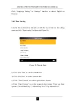
Page 48: ...ault set with the local time In the setting menu to click Time setting as shown in Figure 50 Figure 50 Time Date 1 Click Set Time to set the current time 2 Click Set Date to set the current date 3 Cli...

Page 49: ...it will work until the power is off to automatically shut down If selecting 60 seconds it will work from the last operation After 3 minutes it will automatically enter soft power off into power saving...

Page 50: ...ation Note Restore factory setting will delete all test data and settings All are irrecoverable so please operate it carefully Figure 51 Restore Factory Setting 4 Daily Maintenance 1 The instrument is...

Page 51: ...one year 4 The instrument has built in lithium battery If you do not use the instrument for a long time please charge it every 2 weeks to protect the performance of lithium batteries for extending th...

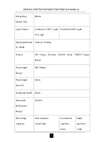
Page 52: ...CMOS Image Sensor G USB Bluetooth 4 0 compatible with 2 1 dual mode widely useful H Super stain resistant and stable standard white calibration plate I Large capacity storage space over 20 000 measur...

Page 53: ...ight Combined LED Light Spectrophotomet ric Mode Concave Grating Sensor 256 Image Element Double Array CMOS Image Sensor Wavelength Range 400 700nm Wavelength Interval 10nm Semiband Width 10nm Measure...

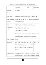
Page 54: ...Colorimetric Index WI ASTM E313 CIE ISO AATCC Hunter YI ASTM D1925 ASTM 313 TI ASTM E313 CIE ISO Metamerism Index MI Staining Fastness Color Fastness Color Strength Opacity 8 Glossiness Observer Angle...

Page 55: ...Measurement Mode Single Measurement Average Measurement Locating Method Camera View Finder Locating Battery Li ion battery 5000 measurements within 8 hours Dimension L W H 184 77 105mm Weight 600g Il...

Page 56: ...RH no condensing Altitude 2000m Storage Environment 20 50 0 85 RH no condensing Standard Accessory Power Adapter Built In Li ion Battery User Guide PC Software White and Black Calibration Cavity Dust...

Page 57: ...V Institutenweg 15 7521 PH Enschede Nederland Telefoon 31 0 900 1200 003 Fax 31 53 430 36 46 info pcebenelux nl www pce instruments com dutch China PCE Beijing Technology Co Ltd 1519 Room 6 Building...

Reviews: