5
3 INSTALLATION OVERVIEW
3.1 Equipment Inspection
Before installing the accelerometer, verify the insulation resistance (I/R) of the sensor is per specification. I/R
can be out of specification due to mishandling and/or damage.
3.2 Polarity Test
Use this test to verify the proper polarity response. Improper polarity will adversely affect the use of the sensor
for machinery diagnostics such as balancing.
Step 1
– Connect the sensor to a 422 style charge amp and any ICP ® signal conditioner. Using standard
cable, connect the powered sensor to an oscilloscope.
Step 2
– Set the time scale to 20 milliseconds/division
Step 3
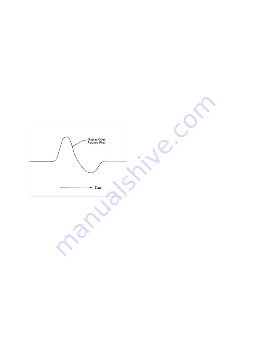
– Hold the transducer in hand and tap the bottom. The wavefrom on the oscilloscope first goes positive
as shown in Figure 1. If the waveform goes negative the wiring is reversed, contact PCB for technical support.
FIGURE 1
3.3 Sensor Location
Characteristics like location, ruggedness, amplitude range, accessibility, temperature, and portability
are extremely critical.
For optimum performance and measurement find a rigid location on the machine casing that most accurately
represents the vibration of the rotor, bearing, fan, etc. to be measured.).
3.4 Mounting Sensor
Bolt mounting requires smooth, flat contact surfaces for proper operation and is recommended for permanent
and/or secure installations. Stud or bolt mounting is also recommended when testing at high frequencies.
Note:
Do NOT attempt mounting on curved, rough, or uneven surfaces, as the potential for misalignment and
limited contact surface may significantly reduc
e the sensor’s upper operating frequency range.
STEP 1: Verify that the ambient and surface temperature of the mounting location are within the
temperature range of the sensor.
Summary of Contents for EX619A11
Page 23: ...DWG 62689 REV NR DIN 44641...
Page 24: ...DWG 62689 REV NR DIN 44641...
Page 25: ...DWG 62689 REV NR DIN 44641...
Page 26: ...DWG 62690 REV NR DIN 44641...
Page 27: ...DWG 62690 REV NR DIN 44641...
Page 28: ...DWG 62690 REV NR DIN 44641...


