background image

32

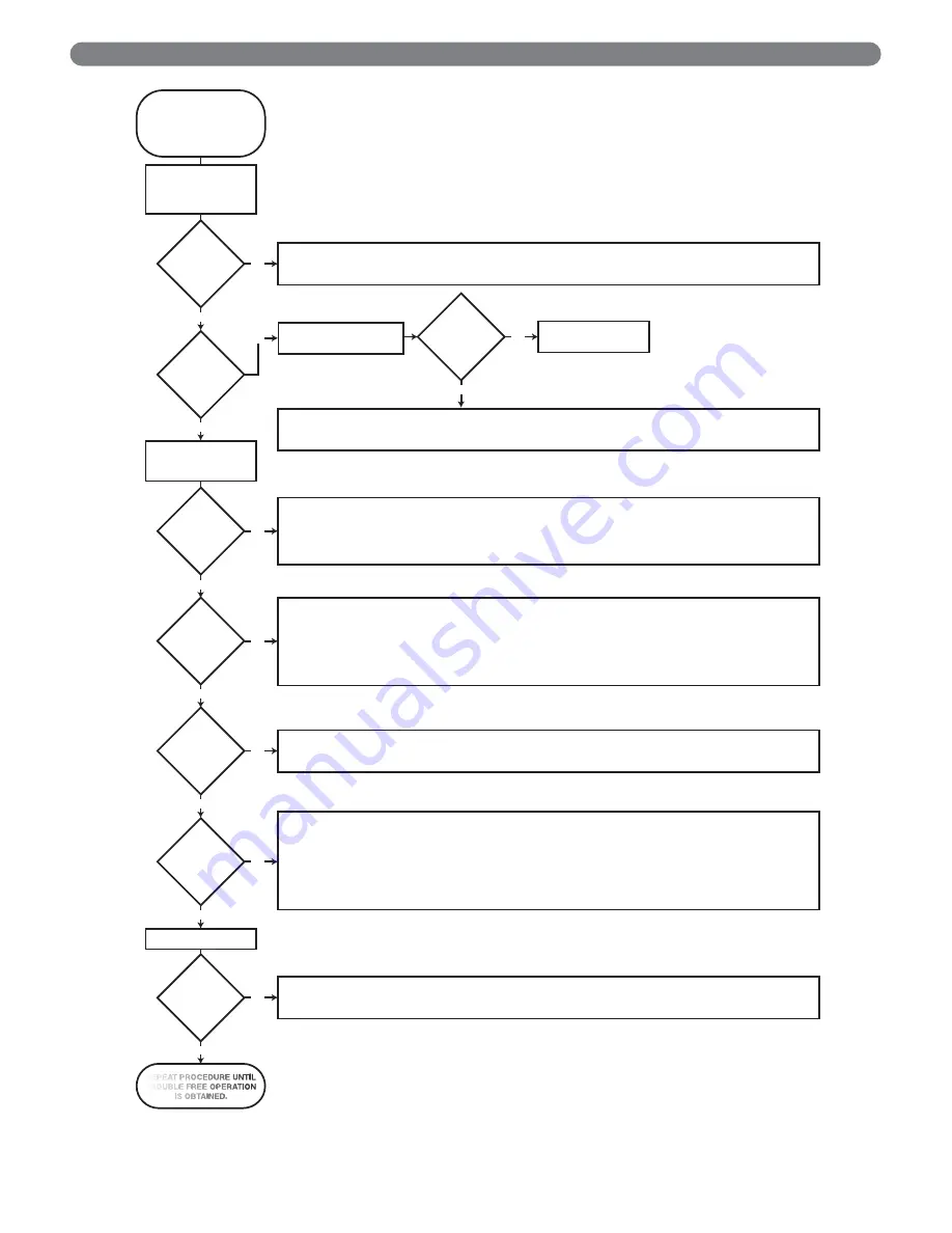
Figure 8.2: Intermittent Ignition System Troubleshooting Sequence

TROUBLESHOOTING

NOTE: 

CALL FOR HEAT

 24 VAC 

S

UPPLY I

S

 CONNECTED TO THE 24 V TERMINAL ON THE CONTROL.

TURN GA

S


S

UPPLY OFF,

TURN THERMO

S

TAT

(CONTROLLER) TO

CALL FOR HEAT.

POWER TO

MODULE? (24 V

NOMINAL)

S

PARK

ACRO

SS


IGNITER/

S

EN

S

OR

GAP?

PILOT BURNER

LIGHT

S

?

S

PARK

S

TOP

S

 WHEN

PILOT I

S

LIT?

S

Y

S

TEM

S

HUT

S

OFF?

S

Y

S

TEM

RUN

S

 UNTIL 

CALL

FOR HEAT

END

S

?

MAIN BURNER

LIGHT

S

?

TURN GA

S


S

UPPLY 

ON  AND RECYCLE 

CALL FOR HEAT.

CALL FOR HEAT

 END

S

CHECK LINE VOLTAGE POWER, LOW VOLTAGE TRAN

S

FORMER, LIMIT CONTROLLER, THERMO

S

TAT (CONTROLLER), AND WIRING AL

S

O.

CHECK AIR PROVING 

S

WITCH ON COMBU

S

TION AIR BLOWER 

S

Y

S

TEM (IF U

S

ED) AND THAT THE VENT DAMPER END 

S

WITCH (IF U

S

ED)

I

S

 MADE.

CHECK IGNITION CABLE, GROUND WIRING, CERAMIC IN

S

ULATOR, AND 

S

PARK GAP ARE CORRECT.

CHECK BOOT OF THE IGNITION CABLE FOR 

S

IGN

S

 OF MELTING OR BUCKLING, TAKE PROTECTIVE ACTION TO 

S

HIELD CABLE

AND BOOT FROM EXCE

SS

IVE TEMPERATURE

S

.

CHECK THAT ALL MANUAL GA

S

 VALVE

S

 ARE OPEN, 

S

UPPLY TUBING AND PRE

SS

URE

S

 ARE GOOD, AND PILOT BURNER

ORIFICE I

S

 NOT BLOCKED (PILOT GA

S

 FLOWING).

CHECK ELECTRICAL CONNECTION

S

 BETWEEN MODULE AND PILOT OPERATOR ON GA

S

 CONTROL.

CHECK FOR 24 VAC ACRO

SS

 PV-MV/PV TERMINAL

S

 ON MODULE. IF VOLTAGE I

S

 OKAY, REPLACE GA

S

 CONTROL. 

IF NOT, REPLACE MODULE.
NOTE: IT MAY BE NECE

SS

ARY TO RECYCLE THE ‘CALL FOR HEAT

 MORE THAN ONCE TO CLEAR THE PILOT 

S

UPPLY TUBE

S

 OF AIR.

NOTE: IF CONTROL GOE

S

 INTO LOCKOUT OR RETRY DELAY, RE

S

ET THE 

CALL FOR HEAT.

CHECK CONTINUITY OF IGNITION CABLE AND GROUND WIRE.
CLEAN FLAME ROD.
CHECK ELECTRICAL CONNECTION

S

 BETWEEN FLAME ROD AND MODULE.

CHECK FOR CRACKED CERAMIC FLAME ROD IN

S

ULATOR.

CHECK THAT PILOT FLAME COVER

S

 FLAME ROD AND I

S


S

TEADY AND BLUE.

ADJU

S

T PILOT FLAME.

IF PROBLEM PER

S

I

S

T

S

 REPLACE MODULE.

CHECK FOR 24 VAC ACRO

SS

 PV-MV/PV TERMINAL

S

 ON MODULE. IF NO VOLTAGE, REPLACE MODULE.

CHECK ELECTRICAL CONNECTION

S

 BETWEEN MODULE AND GA

S

 CONTROL INCLUDING 

S

AFETY CONTROL

S

 WIRED IN THE CIRCUIT. 

IF OKAY, REPLACE GA

S

 CONTROL.

NOTE: IF CONTROL GOE

S

 INTO LOCKOUT OR RETRY DELAY, RE

S

ET THE 

CALL FOR HEAT.

CHECK CONTINUITY OF IGNITION CABLE AND GROUND WIRE.
NOTE: IF GROUND I

S

 POOR OR ERRATIC, 

S

HUTDOWN

S

 MAY OCCUR OCCA

S

IONALLY EVEN THOUGH OPERATION I

S

 NORMAL

AT THE TIME  OF  CHECKOUT.
CHECK THAT PILOT FLAME COVER

S

 FLAME ROD AND I

S


S

TEADY AND BLUE, PILOT FLAME MU

S

T NOT BE MOVING AROUND DUE TO

OUT

S

IDE AIR FLOW

S

, ETC.

ADJU

S

T PILOT FLAME. CHECK GA

S

 PRE

SS

URE MEET

S

 APPLIANCE 

S

PECIFICATION

S

 WHILE APPLIANCE MAIN BURNER ON AND ALL

OTHER GA

S

 APPLIANCE

S

 ON THE 

S

UPPLY ARE OPERATING AT FULL RATE.

IF CHECK

S

 ARE OKAY, REPLACE MODULE.

CHECK FOR PROPER THERMO

S

TAT (CONTROLLER) OPERATION.

REMOVE MV LEAD AT MODULE, IF VALVE CLO

S

E

S

, RECHECK TEMPERATURE CONTROLLER AND WIRING. IF NOT, REPLACE

GA

S

 CONTROL.

YE

S

YE

S

YE

S

YE

S

YE

S

NO

NO

NO

NO

NO

YE

S

YE

S

NO

PULL IGNITION LEAD AND
CHECK 

S

PARK AT MODULE.

S

PARK OK?

NO

REPLACE MODULE

YE

S

S

TART

BEFORE TROUBLE

S

HOOTING, 

FAMILIARIZE YOUR

S

ELF WITH

 THE 

S

TARTUP AND 

CHECKOUT  PROCEDURE

S

.

REPEAT PROCEDURE UNTIL
TROUBLE FREE OPERATION

I

S

 OBTAINED.

NO

Summary of Contents for DE-03

Page 1: ...DE Boilers Series Gas Installation Operation Maintenance Manual ...

Page 2: ... FROM COMMON VENTING SYSTEM 16 5 GAS PIPING 17 6 ELECTRICAL 19 A WIRING 19 B ZONED SYSTEM WIRING 19 C CONTROLS 19 D BOILER SEQUENCE OF OPERATION 21 7 START UP PROCEDURES 22 A COMPLETING THE INSTALLATION 22 B CONTROL DESCRIPTIONS 26 C ADJUSTMENT OF GAS PRESSURE REGULATOR 26 D CHECKING BURNER INPUT 26 E CHECK OUT PROCEDURE 27 8 TROUBLESHOOTING 29 A SHUT DOWN CAUSED BY PILOT OUTAGE PRESSURE SWITCH OR...

Page 3: ...supplement the instructions and make special notice of potential hazards These categories mean in the judgment of PB Heat LLC Indicates special attention is needed but not directly related to potential personal injury or property damage NOTICE Indicates a condition or hazard which will or can cause minor personal injury or property damage CAUTION DANGER Indicates a condition or hazard which will c...

Page 4: ...ols and Safety Devices for Automatically Fired Boilers ANSI ASME CSD 1 NOTICE Do not install this boiler on carpeting Boiler installation on carpeting is a fire hazard Install this boiler on non combustible flooring or use a combustible floor pan to install this boiler on other non carpeted flooring DANGER Do not install this boiler on combustible flooring unless it is installed on a special combu...

Page 5: ...air infiltration rate of a structure is known the minimum required volume of indoor air for the Series DE Boiler and other fan assisted appliances shall be determined as follows where Ifan Input of the fan assisted appliances in Btu hr ACH air change per hour percent of the volume of the space exchanged per hour expressed as a decimal For appliances other than fan assisted calculate the required v...

Page 6: ...horizontal ducts each opening shall have a minimum free area of 1 in2 per 2000 Btu hr 22 cm2 per 2000 W of total rated input for all appliances in the space See Figure 1 5 b One Permanent Opening Method Provide one permanent opening beginning within 12 inches 305 mm of the top of the space The opening shall communicate directly with the outdoors communicate through a vertical or horizontal duct or...

Page 7: ...l louvers and grilles will have 75 free area iii Nonmotorized dampers shall be fixed in the open position b Motorized dampers shall be interlocked with the equipment so that they are proven in the full open position prior to ignition and during operation of the main burner i The interlock shall prevent the main burner from igniting if the damper fails to open during burner startup ii The interlock...

Page 8: ...e with the exhaust vent terminal for the horizontally vented gas fueled heating appliance or equipment The sign shall read in print size no less than one half 1 2 inch in size GAS VENT DIRECTLY BELOW KEEP CLEAR OF ALL OBSTRUCTIONS EXEMPTIONS to the requirements listed above The above requirements do not apply if the exhaust vent termination is seven 7 feet or more above finished grade in the area ...

Page 9: ...nstallation position before removing crate 3 If using combustible floor pan position pan on foundation or flooring 4 Separate the wood shipping pallet from the boiler base by removing two 2 hold down bolts at each end of the boiler base 5 Move boiler into final position If using combustible floor pan install boiler on pan as outlined in the instructions included with the pan 2 BOILER SET UP 7 ...

Page 10: ...e the return to the inlet connection of the circulator 3 Supply Piping Pipe the supply to the 1 1 2 NPT supply tapping at the top of the boiler 4 When system return water temperature will be below 130 F 54 C pipe the boiler with a bypass arrangement to blend the system return and hot supply to obtain at least 130 F 54 C entering the boiler For more information on bypass piping consult the PB Heat ...

Page 11: ... the boiler water during the cooling cycle 9 If this boiler is installed above radiation level provide a low water cutoff device either as a part of the boiler or at the time of boiler installation B SAFETY RELIEF VALVE 1 Locate safety relief valve and fittings in bag assembly 2 If air elimination is not required at the safety relief valve tapping install valve and piping as shown in Figure 3 3 3 ...

Page 12: ...ystem layouts 2 Run each zone pipe down then up to zone to prevent air accumulation in piping 3 If required provide means to isolate and drain each zone separately Figure 3 5 Zone Piping with Zone Valves Figure 3 6 Zone Piping with Circulators WATER PIPING AND CONTROLS 10 ...

Page 13: ...be freeze protected 1 Glycol in hydronic applications is specially formulated for this purpose It includes inhibitors which prevent the glycol from attacking metallic system components Make certain that the system fluid is checked for the correct glycol concentration and inhibitor level 2 The antifreeze solution should be tested at least once a year and as recommended by the antifreeze manufacture...

Page 14: ...rovided by installer 5 Single wall vent pipe should be furnished between increaser and chimney If the vent connector shall be located in or pass through a cold area the vent connector shall be type B material C DIRECT EXHAUST HORIZONTAL VENTING 1 This vent system will operate with a positive pressure in the vent pipe Follow vent pipe manufacturers instructions for proper assembly of vent pipe and ...

Page 15: ...al ou une méthode équivalente afin de l empêcher de s affaisser Ne pas visser dans le tuyau de ventilation Horizontal portions of the vent pipe must be supported at intervals no greater than four feet to prevent sagging separation Parties horizontales du conduit d évacuation doit être soutenu à intervalles ne dépassant pas quatre pieds pour éviter tout affaissement séparation Secure vent pipe to t...

Page 16: ...lent Vent Length 7 Refer to Figure 4 2 for vertical offset option The maximum offset is 5 feet With the exception of the last 90 elbow which serves as the vent terminal the additional elbows and straight vent pipe must be considered when determining maximum vent length Provide a horizontal drain tee as described in Section D Direct Exhaust Vertical Venting Figure 4 2 Direct Exhaust Sidewall Ventin...

Page 17: ...tal portions of the vent pipe shall slope upward from the boiler towards the vertical vent not less than 1 4 per foot 21 mm per meter Parties horizontales de l évent doit pente ascendante de la chaudière vers la cheminée verticale d au moins 1 4 par pied 21 mm par mètre 6 Provide a horizontal drain tee in the horizontal vent run Use silicone drain hose with a 3 76 mm diameter loop trap with a wate...

Page 18: ...s registres de foyers d Place in operation the appliance being inspected Follow the lighting instructions Adjust thermostat so appliance will operate continuously Mettre en service l appareil à inspecter Suivre les instructions concernant l allumage Régler le thermostat afin que l appareil fonctionne sans arrêt e Test for spillage at the draft hood relief opening after 5 minutes of main burner ope...

Page 19: ...equires such a valve a suggested location is shown in Figure 5 1 7 Check piping for leaks Use an approved gas detector a non corrosive leak detection fluid or other leak detection method If leaks are found turn off all gas flow and repair as necessary 8 Disconnect the boiler and its individual shut off valve from the gas supply piping system during any pressure testing of that system at test press...

Page 20: ...03 DE 04 DE 05 DE 06 28 42 56 66 0 8 1 2 1 6 1 9 Pipe Length in Feet Meters Pipe 1 Pipe 1 Pipe 1 Pipe 10 3 0 20 6 1 30 9 1 40 12 2 50 15 2 60 18 3 278 7 9 190 5 4 152 4 3 130 3 7 115 3 3 105 3 0 520 14 7 350 9 9 285 8 1 245 6 9 215 6 1 195 5 5 1050 29 7 730 20 7 590 16 7 500 14 2 440 12 5 400 11 3 1600 45 3 1100 31 1 890 25 2 760 21 5 670 19 0 610 17 3 Specific Gravity 0 50 0 55 0 60 0 65 0 70 0 7...

Page 21: ...harness as required ELECTRICAL 6 ELECTRICAL This unit when installed must be electrically grounded in accordance with the requirements of the authority having jurisdiction or in the absence of such requirements with the current edition of the National Electrical Code ANSI NFPA 70 and or the Canadian Electrical Code Part 1 CSA C22 1 Electrical Code NOTICE Figure 6 1 Wiring Controls and Safety Devic...

Page 22: ...Figure 6 2 Wiring Diagram Spark Ignited Pilot Becket 7600 Limit Control Figure 6 3 Wiring Diagram Spark Ignited Pilot Hydrolevel 3200 Limit control ELECTRICAL 20 ...

Page 23: ... relay energizes blower 5 Negative pressure induced by blower switches Pressure Switch continuing power through closed contacts BR 2 and flame roll out switch 6 Gas valve energizes a Ignitor on b Pilot gas on igniting pilot 7 Pilot flame detected a Ignitor off b Main gas on igniting main burners Note If pilot flame is not detected within 90 seconds the igniter and pilot are turned off for 5 minute...

Page 24: ...ck joints and fittings throughout the system for leaks If leaks are found drain the system and repair as required 8 Connect a manometer to the gas valve inlet pressure tap See Figure 7 2 9 Confirm that the gas supply pressure to the boiler is above the minimum and below the maximum values for the gas being used See the end of Section 5 for these values If a supply pressure check is required isolat...

Page 25: ...Figure 7 1 Gas Valve Manifold and Burner Assembly Intermittent Ignition Figure 7 2 Valve Tapping and Adjustment Screw Locations START UP PROCEDURES 23 ...

Page 26: ...START UP PROCEDURES Figure 7 3 Operating Instructions 24 ...

Page 27: ...25 Figure 7 4 Operating Instructions START UP PROCEDURES ...

Page 28: ...anifold set manifold pressure as follows for various gases a Natural Gas 3 5 W C 0 9 kPa b LP Gas 10 0 W C 2 5 kPa 2 To adjust gas pressure turn adjusting screw of gas pressure regulator counterclockwise to decrease pressure clockwise to increase pressure Refer to Figure 7 2 for location of gas pressure regulator Replace the cap screw when adjustment is complete 3 In no case should the final manif...

Page 29: ...566 cubic meters of gas through the meter Burner inputs in Btu hr for various meter timings and heating values Tables based on 2 cubic feet of gas through the meter Time that meter is read sec Heat Value of Gas MJ cubic meter 37 26 38 19 39 12 25 30 35 40 45 50 55 60 65 70 75 80 85 90 95 100 105 110 115 120 125 84 36 70 30 60 25 52 72 46 86 42 18 38 34 35 15 32 44 30 13 28 12 26 36 24 81 23 43 22 ...

Page 30: ...r the system 6 Do not allow the system controls to subject the boiler to excessively low water temperatures which would cause condensation of flue gases and corrosion of the boiler Operate the boiler at a temperature above 130 F 55 C Adjust the boiler limit as required to maintain boiler temperature above this level 7 Check the general condition of the system including piping support joints etc Ch...

Page 31: ...essure as shown in Figure 8 1 Note that as boiler operates suction pressure will decrease Measure after 15 minutes of boiler operation TROUBLESHOOTING 8 TROUBLESHOOTING Should overheating occur or the gas supply fail to shut off do not turn off or disconnect the electrical supply to the pump This may aggravate the problem and increase the likelihood of boiler damage Instead shut off the gas supply...

Page 32: ...30 TROUBLESHOOTING Figure 8 1 Procedure For Measuring Fan Suction Pressure SEE TABLE 7 ...

Page 33: ...ack or burning at orifice spuds 1 Manifold gas pressure too low 2 Improperly sized drilled orifice spuds 3 Leaking gas valve 4 Burrs on orifice 5 Low supply gas pressure 6 Draft problems in boiler room 1 Adjust to proper pressure 2 Install correct spuds 3 Replace valve 4 Remove burrs 5 Contact gas supplier if natural gas 6 Check air supply ventilation and venting system Delayed ignition 1 Insuffic...

Page 34: ...GOES INTO LOCKOUT OR RETRY DELAY RESET THE CALL FOR HEAT CHECK CONTINUITY OF IGNITION CABLE AND GROUND WIRE CLEAN FLAME ROD CHECK ELECTRICAL CONNECTIONS BETWEEN FLAME ROD AND MODULE CHECK FOR CRACKED CERAMIC FLAME ROD INSULATOR CHECK THAT PILOT FLAME COVERS FLAME ROD AND IS STEADY AND BLUE ADJUST PILOT FLAME IF PROBLEM PERSISTS REPLACE MODULE CHECK FOR 24 VAC ACROSS PV MV PV TERMINALS ON MODULE IF...

Page 35: ...rovide adequate ventilation Wear a NIOSH MSHA approved respirator Wear long sleeved loose fitting clothing and gloves to prevent skin contact Wear eye goggles Minimize airborne dust prior to handling and removal by water misting the material and avoiding unnecessary disturbance of materials Wash work clothes separately from others Rinse washer thoroughly after use Discard RCF materials by sealing ...

Page 36: ...ated on the left side of the boiler Boiler pressure should never be higher than 5 psi 35 kPa below the rating shown on the safety relief valve 25 psig 172 kPa maximum for a 30 psig 207 kPa rating 45 psig 310 kPa maximum for a 50 psig 345 kPa rating The valve rating can be found on the top of the safety relief valve see Figure 3 1 for location of the safety relief valve Boiler temperature should ne...

Page 37: ...top section makes a tight seal to prevent leakage of the products of combustion h Re install the top jacket panel and vent pipe i Re install burners 2 Inspect entire venting system for corrosion support and joint integrity Repair as necessary Inspect vent termination for any obstruction that may hinder proper venting 3 Check the pilot and main burner flame See Figure 9 1 The pilot should provide a...

Page 38: ...Utilization Efficiency AFUE ratings are based on U S Government test Before purchasing this appliance read important information about its estimated annual energy consumptions or energy efficiency rating that is available from your retailer SERIES DE BOILER RATINGS Series DE Boiler Model Number Input DOE Heating Capacity Net Ratings Water Seasonal Efficiency AFUE MBH kW MBH kW MBH kW DE 03 70 21 5...

Page 39: ...37 This page intentionally left blank ...

Page 40: ...r REPAIR PARTS SERIES DE GAS BOILER Repair parts are available from your local PB Heat LLC distributor or from Parts To Your Door at 1 610 916 5380 www partstoyourdoor com Note Remember to include boiler model number and serial number when ordering parts 11 REPAIR PARTS ...

Page 41: ... Gas DE 03 4 50899 Orifice Spud 56 LP Gas DE 04 6 50899 Orifice Spud 56 LP Gas DE 05 8 50899 Orifice Spud 56 LP Gas DE 06 10 50899 9 Flame Rollout Safety Shut Off Switch 51587 10 Flue Collector Fan Mount DE 03 90195 Flue Collector Fan Mount DE 04 90196 Flue Collector Fan Mount DE 05 90197 Flue Collector Fan Mount DE 06 90198 11 Flue Baffle 8 specify qty 1 51584 12 Flue Collector Blanket Seal speci...

Page 42: ...40 REPAIR PARTS Figure 11 2 Base Burners Manifold ...

Page 43: ... Relief Valve 30 PSI Conbraco 10 408 05 50501 Safety Relief Valve 50 PSI Watts 350 99950 Temperature Pressure Gauge 51774 Conversion Kit DE 06 To Nat from LP 90261 Conversion Kit DE 03 thru DE 05 To Nat from LP 90262 Conversion Kit DE 03 thru DE 06 To LP from Nat 90263 Limit Control Beckett AquaSmart 7600B 50335 Immersion Well Beckett 7600T 50341 Immersion Sensor Beckett 7600P 50339 Limit Control ...

Page 44: ...al is the property of the owner and must be affixed near the boiler for future reference TO THE OWNER This boiler should be inspected annually by a Qualified Service Agency PB HEAT LLC 131 S CHURCH STREET BALLY PA 19503 DE8063 R0 10 14 1M Printed in U S A 2014 PB Heat LLC All rights reserved ...

Reviews: