background image

7

Freitragendes Vordachsystem|

 Self-Supporting Canopy System

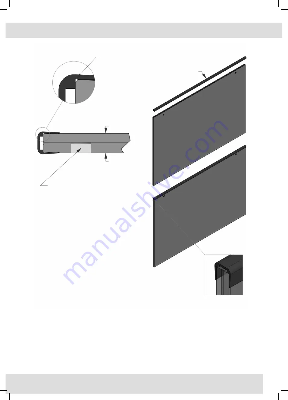
Schritt 6:

Bevor das Glas in das Vordachprofil montiert werden kann, 

muss das hintere Kantenschutzprofil auf das Glas gesteckt wer-

den. Siehe hierzu die Detailansicht. Das hintere Kantenschutz-

profil bitte nach der Montage am Glas mit Gleitmittel CARAM-

BA 6136001 einsprühen. So ist sichergestellt, das es beim 

nächsten Montageschritt keine Komplikationen gibt.

Step 6:

Before the glass can be mounted into the canopy profile, the 

rear edge protection must be clipped onto the glass. See the 

detailed illustration. Please spray the rear edge trim profile after 

mounting the glass with lubricant CARAMBA 6136001. This 

ensures that there are no complications during the next assem-

bly step.

Achten Sie beim Einbau darauf, das diese Kerbe sich auf der Vordachoberseite befindet.

When installing, be sure that this notch is on the top.

HINWEIS!

Bei der Vordach-Glasproduktion ist darauf zu achten, dass 

kein überflüssiges SentryGlas® in die Bohrung (hell grauer 

Bereich) fließt.

Kann dies nicht ausgeschlossen werden, so ist das Sentry-

Glas® im Bereich der Bohrung auszusparen oder nachträg-

lich zu entfernen. Bitte vor Montage durch Sichtkontrolle 

prüfen.

Important note:

During the glass production attention should be paid that 

no surplus SentryGlas® flows into the drillings (light grey 

marked area).

If this cannot be excluded, the SentryGlas® in the areas of 

the drillings has to be either left out or removed afterwards.

Please verify the faultless condition of the drillings through 

visual inspection before installation.

Vordachoberseite

Canopy upper side

hinteres Kantenschutzprofil

Rear edge trim

Vordachunterseite

Canopy lower side

Summary of Contents for SET1510E-17-A

Page 1: ...VD 1510 Freitragendes Vordachsystem Self Supporting Canopy System Montageanleitung Assembly Instructions ...

Page 2: ...rque wrench 1x Endkappe links rechts 1x End cap left right 1x Kantenschutzprofil 1x Edge protection profile 1979ST8 M10 FIS E M10 Innengewindeanker Internal threaded 2x Glassicherung 2x Glass securing fastener mit und ohne VSG Scheibe erhältlich with or without LSG panel available Diese Montageanleitung beschreibt die Montage an einer Be tonwand Weitere Montagemöglichkeiten wie an einem Stahl baut...

Page 3: ...ber geeignetes Befestigungsmaterial Nutzen Sie die Bohrungen des Wandprofils zur Bestimmung der Be festigungsbohrungen Hier ist es sinnvoll mit zwei Personen zu arbeiten Step 1 Align the profile on a suitable substructure using a spirit level Inform yourself in advance of suitable fastening materials Use the holes in the wall profile to determine the mounting holes It is advisable to work with two...

Page 4: ...ie genauen Angaben über Mindestbohrtiefe Bohrdurchmesser etc sind den Daten blättern des Herstellers zu entnehmen Säubern Sie die Bohrlöcher nach dem Bohrvorgang Step 2 Now drill the marked holes Before drilling the holes make sure to know what type of mounting substrate is present The drill hole diameter depends on the type of mounting substrate According to manufacturer there are different mount...

Page 5: ...sonderes Werkzeug erforderlich Bei richtiger Anwendung verklebt der benutzte Injektionsmörtel das Befestigungselement vollflächig mit der Bohrlochwand Step 4 After the injection mortar FIS V 300T is filled as described in step 3 in the drilled holes the internal thread anchor FIS E 15x85 M10 can be inserted into the prepared holes slight rotational movements eases insertion No special tools are re...

Page 6: ...t einem Innensechskantschlüssel SW6 nur Hand fest an Ziehen Sie zum Abschluß alle Schrauben mit einem geeigneten Dremomentschlüssel nach Anzugsmoment 30N m Step 5 After the injection mortar FIS V 300T has cured in the internal threaded anchor the canopy profile can be mounted with the screws DIN 7991 M10x40 Tighten the screws with an Allen key SW6 only hand tight Tighten all screws with the given ...

Page 7: ...step Achten Sie beim Einbau darauf das diese Kerbe sich auf der Vordachoberseite befindet When installing be sure that this notch is on the top HINWEIS Bei der Vordach Glasproduktion ist darauf zu achten dass kein überflüssiges SentryGlas in die Bohrung hell grauer Bereich fließt Kann dies nicht ausgeschlossen werden so ist das Sentry Glas im Bereich der Bohrung auszusparen oder nachträg lich zu e...

Page 8: ...rauben einen geeigneten Stirnlochschlüssel Step 7 Before mounting the glass panel into the canopy profile all preassembled fasteners are to be unscrewed from the profile Use a suitable face spanner alle Fixierelemente mit Hilfe eines geeigneten Stirnlochschlüssel aus dem Profil herausschrauben Remove all fasteners by means of a suitable face spanner from the profile ...

Page 9: ... Hebevorrichtung mit Glas saugern gearbeitet werden Step 8 Press the glass plate with the holes facing downward into the profile and insert it until it stops Be careful that the glass panel is supported in the middle so it does not bend a third person might be necessary Without supporting the middle of the glass panel it may block during inserting If a third person is not available a tilt adjustab...

Page 10: ...ierelemente eingedreht können auch die anderen Fixierele mente gegen das Glas angeschraubt werden Step 9 After the glass panel has been pressed into the canopy profi le the panel can now be aligned by slightly lifting the upper glazing gasket Once the alignment of the glass panel is done screw in the securing fasteners with safety stud The glass panel is now secured from slipping or being pulled o...

Page 11: ...et can be inserted It is advisable to use lube CA RAMBA 6136001 to make this assembly step easier Now the left and right end cover caps can be mounted Remove the protection foil from the adhesive and adhere the end caps to the profile Now secure them to the profile with the provided countersink screws obere Verglasungsdichtung Upper glazing gasket Einbaulage oberes Verglasungsprofil Inserted upper...

Page 12: ... Für Druckfehler und Irrtümer die bei der Herstellung unterlaufen sind ist jede Haftung ausgeschlossen www pauli de Technischer Stand April 2017 Edition B 01 2017 All images technical drawings and descriptions are copyrighted property of the Pauli Sohn GmbH Technical measurements within the catalog are not binding and are subject to change Any liability for printing errors which have occured durin...

Reviews: