23
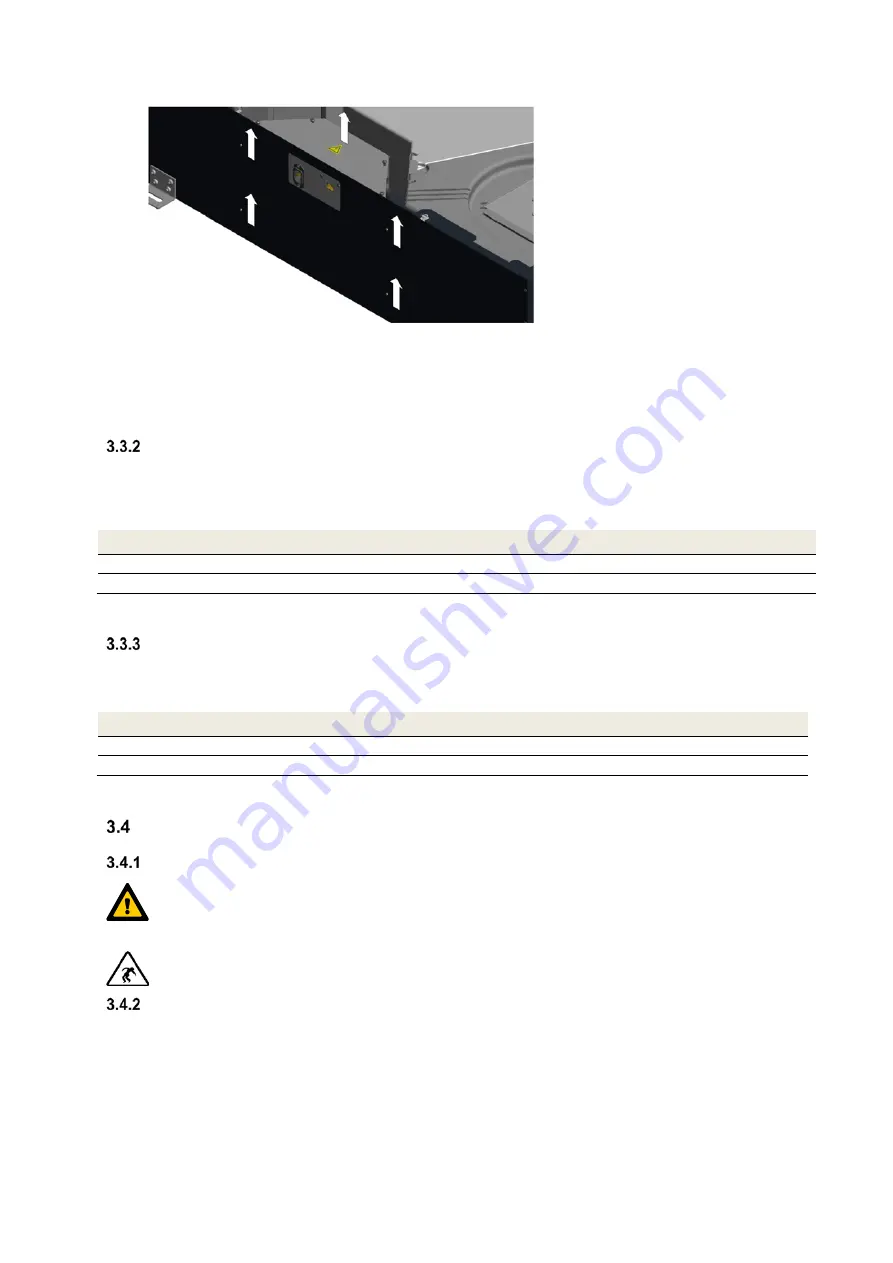
Fig 30: Locking of the control system casing
13. Connect the cables for potential equalisation to the respective flat plugs of the casing parts.
14. Close the casing cover by turning the 4 captive screws of the quarter turn locks
B
by 90°.
15. Re-establish the mains connection.
Connection of external boost ventilation switch
The boost ventilation mode can be activated by actuating one or more boost ventilation switches connected in
parallel. The switches which are usually installed in the design of the respectively used switch range are triggered
when the boost ventilation mode is activated. The potential-free connection between button and connection terminal
of the operating panel is made with an at least 2-strand cable (recommendation: cable type J-Y(ST)Y 2x2x0.6).
Connection terminal operating panel
Wire cable boost ventilation switch
X.07 Ader
1
X.08
Ader 2 (GND)
Tab. 7: Terminal assignment connection boost ventilation switch
Connection of external sensors
A sensor-controlled automatic mode can be operated with an analogue 0-10 V-sensor-signal which is generated by
one or several sensors. The connection between the sensor module and the connection terminal of the operating
panel is made with the cable prescribed for the transmission of the sensor signal.
Connection terminal operating panel
Wire cable sensor module
X.05
Wire 1 (sensor signal 0…10 V)
X.06
Wire 2 (GND)
Tab. 8: Terminal assignment connection analogue sensor signal
Commissioning of the CLIMOS
Operational
readiness
Operational readiness is ensured if the requirements acc. to country-specific regulations are met.
For that purpose, cleanliness of the air duct material, the availability, correct installation and
operational readiness of the entire ventilation equipment provided for the plant must be particularly
ensured.
Check all safety-relevant parts and perform a functional test!
Adjusting the air volume flow
After having verified the operational readiness, the CLIMOS can be commissioned as follows. The scaling of the
available air volume flow in relation to the position of the rotary knob is shown in diagram 1. According to the plant
design the total outside air volume flow is to be laid out as nominal ventilation. This nominal air volume flow should,
according to diagram 2, correspond to a rotary knob position of 4 to 6.


