background image

Introduction

32

SmartNode 5530 User Manual 

4


• Initial Configuration

Introduction

This chapter leads you through the basic steps to set up a new SmartNode and to download a configuration. 
Setting up a new SmartNode consists of the following main steps: 

Note

If you haven’t already installed the SmartNode, refer to Chapter 3, 

"Smart-

Node Installation"

 on page 25. 

Connecting the SmartNode to your laptop PC

Configuring the desired IP address

Connecting the SmartNode to the network

Loading the configuration (optional)

Connecting the SmartNode to Your Laptop PC

First, the SmartNode must be connected to the main power supply with the power cable. Wait until the Power 
LED stops blinking and stays lit constantly. Now the SmartNode is ready. 

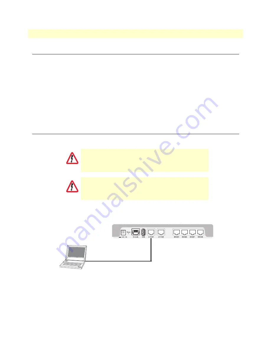
The SmartNode SN5530 is equipped with Auto-MDX Ethernet ports, so you can use straight-through cables 
for host or hub/switch connections (see figure 7).

Figure 7. Connecting the SmartNode to your Laptop PC

The SmartNode comes with a built-in DHCP server to simplify configuration. Therefore, to automatically 
configure the PC for IP connectivity to the SmartNode, the Laptop PC must be configured for DHCP. The 
SmartNode will provide the PC with an IP address. You can check the connection to the SmartNode by execut-
ing the ping command from the PC command window as follows:

ping 192.168.1.1

The interconnecting cables shall be acceptable for external use 
and shall be rated for the proper application with respect to volt-
age, current, anticipated temperature, flammability, and 
mechanical serviceability.

For the ISDN connection to a carrier network, it shall be con-
nected to a network termination device and not connected 
directly to an outside POTS line. 

CAUTION

CAUTION

Straight-through wired cable

LAN (ETH 0/1)

Laptop PC

Summary of Contents for SmartNode 5530 Series

Page 1: ...User Manual Sales Office 1 301 975 1000 Technical Support 1 301 975 1007 E mail support patton com WWW www patton com Part Number 07MSN5530 UM Rev F Revised March 12 2019 This is a Class A device and...

Page 2: ...h license Patton Electronics warrants all SmartNode extender components to be free from defects and will at our option repair or replace the product should it fail within one year from the first date...

Page 3: ...1 3 SmartNode Installation 25 4 Initial Configuration 31 5 Contacting Patton for Assistance 36 A Compliance Information 39 B Specifications 42 C Cabling 48 D Port pin outs 52 E SmartNode SN5530 Factor...

Page 4: ...plication Multi service ISDN Secure VoIP and Data Routing Solution 23 3 SmartNode Installation 25 Planning the Installation 26 Site log 26 Network information 26 Network Diagram 26 IP related informat...

Page 5: ...aration of Conformity 40 Authorized European Representative 40 ISDN Compliance 41 B Specifications 42 DSP 43 Voice Connectivity 43 Data Connectivity 43 WAN Interface if applicable 43 Voice Processing...

Page 6: ...the SmartNode device when it is operating and the Power LED is lit 60 Resetting the SmartNode device when it is initially powered off 60 Very exceptional case minimal config recovery 61 G End User Lic...

Page 7: ...g Solution 23 6 Power LEDs 30 7 Connecting the SmartNode to your Laptop PC 32 8 Connecting the SmartNode to the network 34 9 Connecting a serial terminal 49 10 Typical Ethernet straight through cable...

Page 8: ...rk Mask Configuration 33 6 WAN Interface Specifications 43 7 10 100 Base T RJ 45 socket 53 8 1000Base T RJ 45 Socket 54 9 VDSL ADSL Port RJ 45 connector 54 10 EFM Port 54 11 RJ 45 Socket 55 12 Results...

Page 9: ...pter 3 on page 25 provides quick start hardware installation procedures Chapter 4 on page 31 provides quick start procedures for configuring the SmartNode eSBC IAD Chapter 5 on page 36 contains inform...

Page 10: ...azard symbol and CAUTION heading indicate a potential electric shock hazard Strictly follow the instructions to avoid property damage caused by electric shock The alert symbol and CAUTION heading indi...

Page 11: ...ch the end away from the Smart Node first Before handling the device disconnect the telephone network cables to avoid contact with telephone line voltages When detaching the cables detach the end away...

Page 12: ...er gef hrlicher Spannung ste hen unabh ngig davon ob das Ger t ein oder ausgeschaltet ist PSTN bezieht sich auf Schnittstellen wie Telefon FXS FXO DSL xDSL T1 E1 ISDN Voice usw Diese sind als gef hrli...

Page 13: ...d keywords are in boldface font Helvetica bold italic type Parts of commands which are related to elements already named by the user are in boldface italic font Italicized Helvetica type Variables for...

Page 14: ...14 Chapter 1 General Information Chapter contents SmartNode SN5530 Overview 15 Model Code Conventions 16 Rear panel ports 17 Front panel LEDs 19...

Page 15: ...ons Four up to 16 channels of Voice over IP and local voice switching via 2 4 or 8 ISDN BRI S0 T0 ports Each port can be switched between NT and TE per software For each ISDN port in NT mode a Phantom...

Page 16: ...Some IAD versions also have WAN uplink termination included such as Fiber SFP ADSL VDSL or G SHDSL EFM ATM On the product the following model code conventions apply V stands for number of Voice Chann...

Page 17: ...530 Overview 17 SmartNode 5530 User Manual 1 General Information Rear panel ports Figure 2 shows examples of SN5530 rear panels The ports are described in table 2 on page 18 Figure 2 Examples of SN553...

Page 18: ...NT mode The interface is internally terminated with 100 Ohm Point to point or point to multipoint configurable If the port is in NT mode a Phantom power supply can be switched on to supply connected...

Page 19: ...P EUI SN5531 8BIS16VHP EUI V o IP A U X 1 A U X 2 E T H 0 G I G 0 E T H 1 G I G 1 0 0 0 1 0 2 0 3 0 4 0 5 0 6 0 7 Voice Ports P o w e r V o IP A U X 1 A U X 2 E T H 0 G IG 0 E T H 1 G IG 1 0 0 0 1 0 2...

Page 20: ...evice has registered to the SN5530 Off indicates the unit is not configured or registered or has no active direct routed VoIP connection BRI 0 BRI 7 On when L1 and L2 are active Flashes when there are...

Page 21: ...er 2 Applications Overview Chapter contents Introduction 22 Application Edge Intelligence of Enterprise Communication 22 How it works 23 Application Multi service ISDN Secure VoIP and Data Routing Sol...

Page 22: ...ns Bypassing the PSTN Using Internet telephony service providers ITSPs instead of incumbent carriers dra matically reduces telephony costs IP PBXs with their full suite of features and ease of integra...

Page 23: ...uses the SmartNode as PSTN gateway For all calls from this IP PBX you can direct them to the PSTN or to ITSPs Numbering plan adaptations are handled through regular expression matching by the SmartNo...

Page 24: ...tNode 5530 User Manual 2 Applications Overview Quality of Service QoS features complete the offering with advanced voice prioritization and traffic manage ment Patton s patent pending DownStreamQoS en...

Page 25: ...the Patton SmartNode eSBC IAD 27 Placing the SmartNode device 27 Installing cables 28 Connecting ISDN terminals and NT to the SmartNode s ISDN BRI ports 28 Connecting the 10 100 1000Base T Ethernet L...

Page 26: ...include information such as listed in table 4 Network information Network connection considerations that you should take into account for planning are described for several types of network interfaces...

Page 27: ...fers easy access to cables Allow sufficient space at the rear of the chassis for cable connections Additionally you should consider the need to access the unit for future upgrades and maintenance Inst...

Page 28: ...ails on the BRI port pinout and ISDN cables refer to Appendix C Cabling on page 48 and Appendix D Port pin outs on page 52 Connecting the 10 100 1000Base T Ethernet LAN and WAN cables The SmartNode SN...

Page 29: ...option for an SFP for Fiber WAN module see details about the tested and compatible SFP modules on http www patton com products sfpmodules asp Connecting the Power Supply Do the following to connect t...

Page 30: ...mode line power is switched off A total of 4W are available Congratulations you have finished installing the SmartNode Enterprise Session Border Controller Now go to Chapter 4 Initial Configuration o...

Page 31: ...32 Connecting the SmartNode to Your Laptop PC 32 Configure the Desired IP Address 33 Factory default IP Settings 33 Login 33 Changing the WAN IP address 33 Connecting the SmartNode to the Network 34...

Page 32: ...MDX Ethernet ports so you can use straight through cables for host or hub switch connections see figure 7 Figure 7 Connecting the SmartNode to your Laptop PC The SmartNode comes with a built in DHCP...

Page 33: ...et session displays the login screen Type the factory default login admin and leave the password empty Press the Enter key after the password prompt login admin password Enter 192 168 1 1 After you ha...

Page 34: ...onfig 172 16 1 99 if ip WAN The SmartNode can now be connected to your network Connecting the SmartNode to the Network In general the SmartNode will connect to the network via the WAN ETH 0 0 port Thi...

Page 35: ...configuration as described in the configuration note to your network remember to modify the IP address and copy the modified configuration to a TFTP server The SmartNode can now load its configuration...

Page 36: ...ntact information 37 Contacting Patton Technical Services for Free Support 37 Warranty Service and Returned Merchandise Authorizations RMAs 37 Warranty coverage 37 Out of warranty service 38 Returns f...

Page 37: ...gram Note If you purchased your equipment from a Patton Electronics reseller ask your reseller how you should proceed with warranty service It is often more con venient for you to work with your local...

Page 38: ...be issued upon receipt and inspection of the equipment 30 to 60 days We will add a 20 restocking charge crediting your account with 80 of the purchase price Over 60 days Products will be accepted for...

Page 39: ...ndix A Compliance Information Chapter contents Compliance 40 EMC 40 Safety 40 Radio and TV Interference FCC Part 15 40 EC Declaration of Conformity 40 Authorized European Representative 40 ISDN Compli...

Page 40: ...ables try to correct the interference by one or more of the following measures moving the computing equipment away from the receiver re orienting the receiving antenna and or plugging the receiving eq...

Page 41: ...mation ISDN Compliance The device is approved for connection to the public ISDN telecommunication network For the ISDN connection to a carrier network it shall be con nected to a network termination d...

Page 42: ...y 43 Data Connectivity 43 WAN Interface if applicable 43 Voice Processing signalling dependent 45 Fax and modem support 45 Voice Signalling 45 Voice Routing Session Controller 46 IP Services 46 Manage...

Page 43: ...on model R option ISDN line power can be switched on per software per port Data Connectivity Two 10 100 1000Base TX Ethernet ports All ports full duplex autosensing auto MDX WAN Interface if applicabl...

Page 44: ...PoA RFC 1577 2225 PPPoE Client over ATM RFC 2516 IPoA RFC 2684 1483 ATM AAL5 encapsulation Max 8 PVCs User selectable VC MUX and LLC MUX default Configurable auto connection ATM QoS UBR default CBR an...

Page 45: ...28 ms Four eight or 16 simultaneous low bandwidth voice or T 38 fax calls DTMF detection and generation Carrier tone detection and generation Silence suppression and comfort noise Adaptive and configu...

Page 46: ...rmation elements IEs of the ISDN setup Wildcard and regular expression matching Regular expression number manipulation functions Replace numbers Add remove digits Pattern matching and replacement IP S...

Page 47: ...ng SNMP v1 agent MIB II and private MIB Built in diagnostic tools trace debug Secure Auto provisioning System Dual Core CPU Broadcom BCM53012 operating at 1GHz Memory 256 Mbytes DRAM 128 Mbytes Flash...

Page 48: ...48 Appendix C Cabling Chapter contents Introduction 49 Serial Console 49 Ethernet 50 ISDN BRI 51...

Page 49: ...ff Note See section Console port on page 53 for console port pin outs The interconnecting cables shall be acceptable for external use and shall be rated for the proper application with respect to volt...

Page 50: ...igure 11 Typical Ethernet straight through cable diagram for 1000Base T The interconnecting cables shall be acceptable for external use an shall be rated for the proper application with respect to vol...

Page 51: ...nterconnecting cables shall be acceptable for external use an shall be rated for the proper application with respect to volt age current anticipated temperature flammability and mechanical serviceabil...

Page 52: ...outs Chapter contents Introduction 53 Console port 53 Ethernet 53 VDSL ADSL Port A and AVA AVB models only 54 G SHDSL EFM ATM port 2G and 4G models 54 Fiber Ports F models only 55 ISDN BRI NT Net or T...

Page 53: ...Node Console port Figure 13 EIA 561 RJ 45 8 pin port Note N C means no internal electrical connection Console Connection Settings 19200bps 8 bits no parity 1 stop bit flow control off Ethernet Note Pi...

Page 54: ...l 1 TRD0 2 TRD0 3 TRD1 4 TRD1 5 TRD2 6 TRD2 7 TRD3 8 TRD3 Table 9 VDSL ADSL Port RJ 45 connector Pin Signal 4 Tip 5 Ring Table 10 EFM Port Pin Signal Pair 1 Tip 1 2 Ring 1 3 Tip 2 4 Tip 0 5 Ring 0 6 R...

Page 55: ...uring power failure Fallback relay operation depending on model Only for Models with R in Product code When the unit is not powered the fallback relay connects pins 3 4 5 and 6 of the net and the user...

Page 56: ...56 Appendix E SmartNode SN5530 Factory Configuration Chapter contents Introduction 57...

Page 57: ...factory configuration settings for SmartNode SN5530 can be obtained with the following command through the CLI login admin password Enter 192 168 1 1 show config shipping config Refer to Chapter 4 In...

Page 58: ...ons Chapter contents Introduction 59 Resetting the SmartNode device when it is operating and the Power LED is lit 60 Resetting the SmartNode device when it is initially powered off 60 Very exceptional...

Page 59: ...Power LED is lit on page 60 Factory reset which is followed by a device reboot as indicated by the fast blinking of all LEDs see section Resetting the SmartNode device when it is operating and the Pow...

Page 60: ...wer to the SmartNode device The Power LED flashes quickly for 2 seconds during which time the Reset button must remain pressed 2 The Power LED will begin a series of blink pattern starting with 1 blin...

Page 61: ...SmartNode device The Power LED flashes quickly for 2 seconds during which time the Reset button must remain pressed 2 The Power LED will begin a series of blink patterns starting with 1 blink pause 3...

Page 62: ...d up the device will run using the minimal config Minimal configuration file cli version 4 00 telnet server shutdown ssh server no shutdown web server http shutdown web server https shutdown context i...

Page 63: ...ent Chapter contents End User License Agreement 64 1 Definitions 64 2 Title 64 3 Term 64 4 Grant of License 64 5 Warranty 65 6 Termination 65 7 Notices 65 8 Other Licenses 65 9 Unenforceable Provision...

Page 64: ...re but are standard commercial software Except for the license use rights otherwise expressly provided in this Agreement no right title or interest in Patton Licensed Products is granted hereunder Lic...

Page 65: ...ing all copies of the licensed Program s B Patton Electronics Company may terminate this Agreement should End User violate any of the provi sions of section 4 Grant of License on page 64 C Upon termin...

Page 66: ...rrevocably submits to the exclusive jurisdiction of the courts of the State of Maryland USA for any dispute arising under or relating to this agreement and waives user s right to institute legal proce...

Reviews: