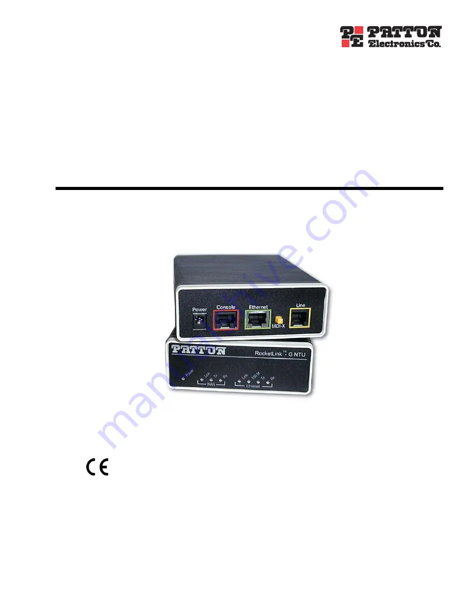
background image


Model 3088/I


RocketLink-G G.SHDSL NTU


Getting Started Guide


Sales Office:


+1 (301) 975-1000


Technical Support:


+1 (301) 975-1007


E-mail:


[email protected]


WWW:


www.patton.com


Document Number: 


03332U1-001 Rev. C


Part Number: 


07M3088/I-GS


Revised: 


October 15, 2008


Important


This is a Class A device and is intended for use in a light industrial environment. It is not intended nor approved for use in an industrial 
or residential environment.


Start Installation

For Quick 


Summary of Contents for 3088/I

Page 1: ...support patton com WWW www patton com Document Number 03332U1 001 Rev C Part Number 07M3088 I GS Revised October 15 2008 Important This is a Class A device and is intended for use in a light industri...

Page 2: ...e product should it fail within one year from the first date of shipment This warranty is limited to defects in workmanship or materials and does not cover customer damage abuse or unauthorized modifi...

Page 3: ...nd status 28 5 Installation operation 32 6 System Management 36 7 Diagnostic tools 41 8 Contacting Patton for assistance 43 A Compliance information 46 B Specifications 49 C Factory replacement parts...

Page 4: ...n 16 Introduction 17 Power up the NTU 17 AC power up 17 DC power up 17 Power up indication 18 Configure the IP address 18 Connect a PC and log in 18 Modify the IP address 19 Connect to the local IP ne...

Page 5: ...nk G Plug n Play 37 Saving the configuration 38 Reset for Factory Default 38 Console 38 Backing up and restoring saved configurations 39 Authentication 39 System Software Upgrade 40 7 Diagnostic tools...

Page 6: ...aracteristics 50 Ethernet 50 Protocol support 50 Management 51 10Base T 100Base TX interface 51 Serial connector 51 Diagnostics 51 Status LEDs 51 Power 51 WAN Link 51 WAN Tx 51 WAN Rx 51 Ethernet Link...

Page 7: ...7 3088 I Getting Started Guide Table of Contents RJ 45 shielded 10 100 Ethernet port 59 F RS 232 console interface pin assignments 60 RS 232 console interface pin assignments 61...

Page 8: ...26 13 Clearing the error counters 27 14 Configuration of the IP address and subnet mask 29 15 Enabling Bridged PPP over the DSL link 29 16 Ethernet performance statistics 30 17 Top of web page for co...

Page 9: ...9 List of Tables 1 General conventions 13...

Page 10: ...n page 36 describes how to configure the RocketLink G NTU save the configuration reset the NTU to the factory default condition and upgrade the system software Chapter 7 on page 41 describes the syste...

Page 11: ...calls attention to important information The alert symbol and CAUTION heading indicate a potential haz ard Strictly follow the instructions to avoid property damage The shock hazard symbol and CAUTION...

Page 12: ...be easily accessible and protected by a circuit breaker If an AC power adapter is used ensure that the power cable used meets all applicable standards for the country in which it is to be installed a...

Page 13: ...ding Clicking on the hyperlink jumps you to the reference When you have finished reviewing the reference click on the Go to Previous View button in the Adobe Acrobat Reader toolbar to return to your s...

Page 14: ...14 Chapter 1 General information Chapter contents RocketLink G 3088 I overview 15 Features 15...

Page 15: ...e RocketLink DSL offers equal data rates in both directions over a single twisted pair using TC PAM modulation Line connection is made through the RJ 11 jack Standard versions of Model 3088 I are powe...

Page 16: ...on 17 Power up the NTU 17 AC power up 17 DC power up 17 Power up indication 18 Configure the IP address 18 Connect a PC and log in 18 Modify the IP address 19 Connect to the local IP network 19 Log on...

Page 17: ...lso refer to Power up on page 33 AC power up 1 Connect female plug of the AC power cord to the AC adaptor provided 2 Connect the barrel type connector of the AC adaptor to the barrel type power jack o...

Page 18: ...C s serial port to the RocketLink G s Console port red outline see figure 4 Figure 4 Connecting RocketLink G NTU to the PC s serial port There are no user servicable parts in the power supply section...

Page 19: ...face ip1 ipaddress 10 10 4 10 255 255 255 0 Note The above IP address 10 10 4 10 24 is only an example You must choose an IP address on the same subnet as your PC 3 Verify the new address is correct a...

Page 20: ...n step 2 of section Modify the IP address on page 19 In this example 10 10 4 10 see figure 6 Figure 6 RocketLink G web management home page 2 Log in to the web management home page using the username...

Page 21: ...e connected back to back one must be con figured as Remote the other as Central 7 The WAN Link LED will flash while in the process of establishing a link The LED will be on constantly once a valid DSL...

Page 22: ...nd status Chapter contents DSL configuration 23 DSL Parameters 23 DSL Error Monitor Configuration 24 G SHDSL Status 25 Run Time Statistics 25 DSL Line Error Counters 26 Local Interface Error Counters...

Page 23: ...hannel specified in the G 991 2 standard for SHDSL We use standard EOC messages for our remote loopback The 3088 I also supports proprietary EOC messages that allow a 3096RC to configure it Intended D...

Page 24: ...threshold The error monitor inspects Total Intervals intervals before it stops Note Setting Max Interval Errors to 0 disables the error monitor and setting Total Intervals to 0 causes the error monit...

Page 25: ...ical DSL link the field is TRUE If not it displays FALSE Loss Of Signal Indicates Signal Loss or Signal Found Loss of Sync Indicates whether the Sync Word is synchronized DLS Sync State The sync state...

Page 26: ...that synchronization has been lost since the error counters have been cleared CRC Errors Shows the number of CRC errors that have occurred since either startup or the last time that error counters we...

Page 27: ...de 3 G SHDSL config and status Clearing Error Counters The error counters may be cleared in the Configuration web page or here in the Status web page Select Clear All Counters and click on the Submit...

Page 28: ...hapter 4 Ethernet WAN PPP config and status Chapter contents IP configuration 29 PPP configuration 29 Ethernet port configuration 29 Ethernet Basic Port Attributes 29 Ethernet Advanced Port Attributes...

Page 29: ...on volatile memory See Saving the configuration on page 38 Figure 14 Configuration of the IP address and subnet mask PPP configuration Also found in the Configuration web pages is the parameter for en...

Page 30: ...tatistics Ethernet Advanced Port Attributes While in the page for the Ethernet Basic Port Attributes click on View advanced attributes to view many additional parameters which include three configurab...

Page 31: ...Ethernet port configuration 31 3088 I Getting Started Guide 4 Ethernet WAN PPP config and status Figure 18 Configurable Ethernet parameters...

Page 32: ...s Installation 33 Connecting the twisted pair interface 33 Operation 33 Power up 33 LED status indicators 34 Power Yellow 34 WAN LEDs 34 Link Yellow 34 Tx Yellow 34 Rx Yellow 34 Ethernet LEDs 35 Link...

Page 33: ...endix D on page 56 Operation Once the Model 3088 I is properly configured and installed it should operate transparently This section describes information for powering the 3088 I reading the LED statu...

Page 34: ...enter normal operation and the LED blinks once every 0 4 seconds WAN LEDs There are three WAN LEDs Link Tx and Rx Link Yellow The Link LED glows solid while a DSL link is established While the DSL lin...

Page 35: ...tion of the MDI X switch on the rear panel If the LED still fails to light your cable may be faulty 100M Yellow The Link LED glows solid if the 100Mbps Ethernet link has been negotiated If there is no...

Page 36: ...Management Chapter contents RocketLink G Plug n Play 37 Saving the configuration 38 Reset for Factory Default 38 Console 38 Backing up and restoring saved configurations 39 Authentication 39 System S...

Page 37: ...re itself to the DTE rate Bandwidth Allocation defined at the Model 3096RC Other configuration parameters remain in the default setting Follow the instructions below to activate RocketLink Plug n Play...

Page 38: ...ck on the Reset hyperlink in the System Management menu If you want to reset to factory default settings check the box for that function See figure 22 Click on the Restart button Wait until the 3088 I...

Page 39: ...have the option of either viewing the configuration file or saving it directly to your PC See figure 23 To execute the reverse operation click on the Browse button find and select the configuration fi...

Page 40: ...select the desired software version on your PC Subsequently click on Update to invoke the upgrade process It is Essential to wait until the upgrade is completed before attempt ing any access of the 3...

Page 41: ...41 Chapter 7 Diagnostic tools Chapter contents LED status monitor definition 42 System tools for testing 42 Ping Traceroute 42 Clearing error counters 42...

Page 42: ...ools which are described in this section Ping Traceroute Ping and Traceroute are familiar to all IP network users Go to the Tools hyperlink under System Management in the Configuration Menu You will f...

Page 43: ...n support headquarters in the USA 44 Alternate Patton support for Europe Middle East and Africa EMEA 44 Warranty Service and Returned Merchandise Authorizations RMAs 44 Warranty coverage 44 Out of war...

Page 44: ...1 253 663 5693 Alternate Patton support for Europe Middle East and Africa EMEA Online support available at www patton inalp com E mail support e mail sent to support patton inalp com will be answered...

Page 45: ...be issued upon receipt and inspection of the equipment 30 to 60 days We will add a 20 restocking charge crediting your account with 80 of the purchase price Over 60 days Products will be accepted for...

Page 46: ...n Chapter contents Compliance 47 EMC 47 Safety 47 PSTN Regulatory 47 FCC Part 68 ACTA Statement 47 Radio and TV Interference FCC Part 15 47 Industry Canada Notice 48 CE Declaration of Conformity 48 Au...

Page 47: ...a complaint with the FCC if you believe it is necessary The telephone company may make changes in its facilities equipment operations or procedures that could affect the operation of the equipment If...

Page 48: ...le to be con nected to the facilities of the local telecommunications company The equipment must also be installed using an acceptable method of connection In some cases the company s inside wiring as...

Page 49: ...ment 51 10Base T 100Base TX interface 51 Serial connector 51 Diagnostics 51 Status LEDs 51 Power 51 WAN Link 51 WAN Tx 51 WAN Rx 51 Ethernet Link 51 Ethernet 100M 52 Ethernet Tx 52 Ethernet Rx 52 Powe...

Page 50: ...d factory default option Standard 1 year warranty G SHDSL characteristics 4 6 Mbps maximum speed over 2 wire Data rates from 192 kbps to 4 608 Mbps Annex A ANSI Annex B ETSI PSD selection 2 wire suppo...

Page 51: ...aceroute facilities DSL run time statistics DSL line error counters Local interface error counters Bridged PPP statistics Ethernet port statis tics and front panel status LEDs see section Status LEDs...

Page 52: ...onal power cords are available for the universal power supply Please refer to Appendix C on page 54 for country specific power cords The Model 3088 I powers up as soon as it is plugged into an AC outl...

Page 53: ...ndix D on page 56 Line Coding TC PAM 16 Trellis Coded Pulse Amplitude Modulation for rates from 192 kbps to 2 304 Mbps TC PAM 32 for rates above 2 304 Mbps Line Interface Transformer coupled 2500 VRMS...

Page 54: ...54 Appendix C Factory replacement parts and accessories Chapter contents Factory replacement parts and accessories 55...

Page 55: ...EUR European Power Cord CEE 7 A 0805UK United Kingdom Power Cord D 0805US American Power Cord K 0805AUS Australia New Zealand Power Cord C 0805DEN Denmark Power Cord E 0805FR France Belgium Power Cord...

Page 56: ...56 Appendix D RJ 11 non shielded DSL port Chapter contents RJ 11 non shielded DSL port 57...

Page 57: ...d DSL port 57 3088 I Getting Started Guide D RJ 11 non shielded DSL port RJ 11 non shielded DSL port Single twisted pair TP for full duplex transmission The signals are polarity insensitive Pin Signal...

Page 58: ...58 Appendix E RJ 45 shielded 10 100 Ethernet port Chapter contents RJ 45 shielded 10 100 Ethernet port 59...

Page 59: ...088 I Getting Started Guide E RJ 45 shielded 10 100 Ethernet port RJ 45 shielded 10 100 Ethernet port Note The following table assumes the MDI X switch is in the out position Pin Signal 1 TX output 2...

Page 60: ...60 Appendix F RS 232 console interface pin assignments Chapter contents RS 232 console interface pin assignments 61...

Page 61: ...1 3088 I Getting Started Guide F RS 232 console interface pin assignments RS 232 console interface pin assignments RJ 45 non shielded Connector EIA 561 Pin Signal 1 DSR out 2 CD out 3 DTR in 4 Signal...

Reviews: