background image

SmartNode 4660 and 4670 Series Front Panels

22

SmartNode 4660 & 4670 User Manual 

1 • General Information

SmartNode 4660 and 4670 Series Front Panels

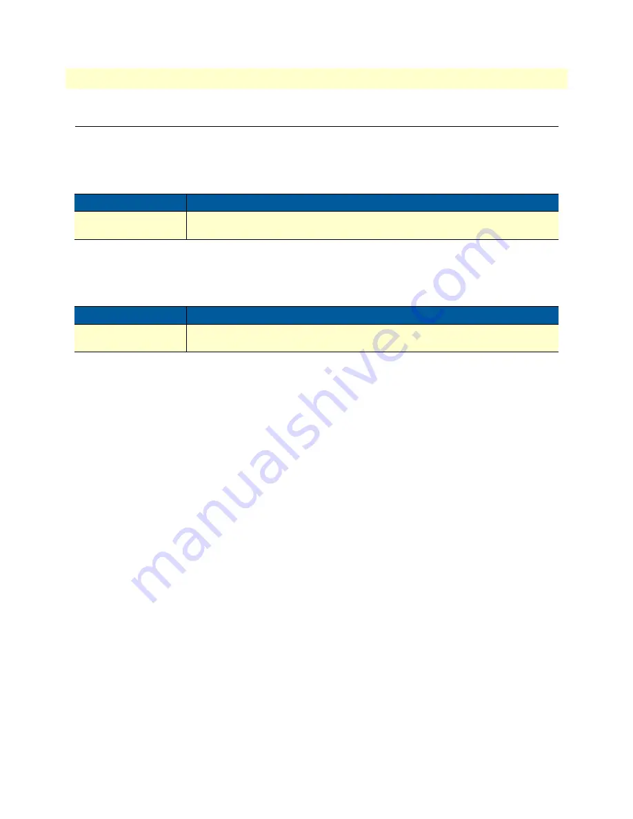
SmartNode 4660 Front panel

The LED definitions are listed in 

Table 8

.

SmartNode 4670 Front panel

The LED definitions are listed in 

Table 8

.

Table 8. SmartNode 4660 LED definitions

LED

Description

Power

When lit, indicates power is applied and the unit is in normal operation. Off indicates 
no power applied. Flashes once per second during boot (startup).

Table 9. SmartNode 4670 LED definitions

LED

Description

Power

When lit, indicates power is applied and the unit is in normal operation. Off indicates 
no power applied. Flashes once per second during boot (startup).

Summary of Contents for 13243D4-001

Page 1: ...on com Part Number 07MSN4660 4670 UM Rev C Revised June 4 2014 This is a Class B device and is intended for use in a light industrial commercial or residential environment It is not intended for use i...

Page 2: ...d under a license and may be used or copied only in accordance with the terms of such license For information about the license see Appendix F End User License Agreement on page 60 or go to www patton...

Page 3: ...panel 24 2 Applications Overview 25 Typical Application 26 3 SmartNode Installation 27 Planning the Installation 28 Site Log 28 Network Information 28 Network Diagram 28 IP Related Information 29 Soft...

Page 4: ...3 Warranty Service and Returned Merchandise Authorizations RMAs 43 Warranty coverage 43 Out of warranty service 44 Returns for credit 44 Return for credit policy 44 RMA numbers 44 Shipping instruction...

Page 5: ...ole 56 Ethernet 56 ISDN BRI NT Net 57 ISDN BRI TE User 57 FXS 57 FXO 58 G SHDSL 58 ADSL 58 EFM 58 Fiber 59 E SmartNode Factory Configuration 60 Introduction 61 F End User License Agreement 62 End User...

Page 6: ...S FXO interface 31 7 Power connector location on rear panel 33 8 Ferrite clamp installation 34 9 SmartNode Discovery Tool window 36 10 SmartNode Discovery Tool window with webbrowser selected 37 11 Lo...

Page 7: ...7 SN4670 LED Definitions 22 8 SmartNode 4660 LED definitions 24 9 SmartNode 4670 LED definitions 24 10 Sample site log entries 28 11 SmartNode weight and maximum power specifications 51 12 Ethernet P...

Page 8: ...pter 3 on page 25 provides hardware installation procedures Chapter 4 on page 33 provides quick start procedures for configuring the SmartNode 4660 and 4670 Chapter 5 on page 40 contains information o...

Page 9: ...tions afin d viter des dom mages mat riels The shock hazard symbol and CAUTION heading indicate a potential electric shock hazard Strictly follow the instructions to avoid property damage caused by el...

Page 10: ...tor power plugs L1 L2 GND or Hot Neutral Safety Protective Ground the wall outlet or socket must have an earth ground Pour les appareils aliment s en ca qui ont 3 prises de courant des conducteurs L1...

Page 11: ...personnel qualifi In accordance with the requirements of council directive 2002 96 EC on Waste of Electrical and Electronic Equipment WEEE ensure that at end of life you separate this product from oth...

Page 12: ...c type Parts of commands which are related to elements already named by the user are in boldface italic font Italicized Futura type Variables for which you supply values are in italic font Futura type...

Page 13: ...atures 15 SmartNode 4660 Series Model Codes 16 SmartNode 4670 Series Model Codes 16 CodesSmartNode 4660 and 4670 Series Rear Panels 17 SmartNode 4660 Rear Panel 17 SmartNode 4670 Rear Panel 19 SmartNo...

Page 14: ...every SmartNode the SN4660 and SN4670 support every industry standard CODEC to deliver toll quality voice on every call Adding session border controller capabilities the SmartNodes include IP transcod...

Page 15: ...fic management and shaping as well as Voice over VPN with AES DES strong encryption for secure toll quality voice communications Standards compliant VoIP in accordance with SIP or H 323 protocols High...

Page 16: ...Table 3 SmartNode 4670 Ports and Voice Channels Model BRI FXS FXO VC Ethernet G SHDSL ADSL Fiber HPC SN4670 4JS4JO8V EUI 4 4 8 4 1 SN4670 8JS8V EUI 8 8 4 1 SN4670 4BIS8V2GS EUI 4 8 4 1 SN4670 4BIS8VA...

Page 17: ...used as fallback if connected to an NT The port can be switched between TE and NT mode The interface is internally terminated with 100 ohm Point to point or point to multipoint configurable If the po...

Page 18: ...with the unit powered off press and hold the Reset button as you apply power to the unit Release the Reset button when the Power LED starts blinking so the unit will enter bootloader mode Table 5 Sma...

Page 19: ...see Figure 2 connects the unit to with an ISDN device over an S T bus e g a PBX or an NT The interface may be used as fallback if connected to an NT The port can be switched between TE and NT mode The...

Page 20: ...ode has a 12V DC 1A power input see Figure 2 Reset The reset button see Figure 2 has three functions Restart the unit with the current startup configuration Press for less than 1 second and release th...

Page 21: ...link is established EFM link LED There are two colours in the Link light on the EFM Daughterboard Red and Green The Green will be showing anytime ANY Link is up and traffic can flow The Red Link will...

Page 22: ...definitions are listed in Table 8 Table 8 SmartNode 4660 LED definitions LED Description Power When lit indicates power is applied and the unit is in normal operation Off indicates no power applied Fl...

Page 23: ...23 Chapter 2 Applications Overview Chapter contents Typical Application 24...

Page 24: ...acy PBX systems while connecting fax separately with both BRI and FXS FXO interfaces on one box Combining a VoIP gateway with an IP router the SmartNode 4660 4670 adds QoS and VPN security making it t...

Page 25: ...n 27 Installing cables 27 Installing an interface cable on the SmartNode s FXS and FXO interface ports 28 Connecting ISDN terminals and NT to the SmartNode s ISDN BRI ports 28 Connecting the 10 100 10...

Page 26: ...already keep such a log Site log entries should include information such as listed in Table 10 Network Information Network connection considerations that you should take into account for planning are...

Page 27: ...C or equivalent with Windows Telnet or a program such as Tera Term Pro Web to configure the software on your SmartNode AC Power Mains If you suspect that your AC power is not reliable for example if r...

Page 28: ...tion for cooling Note For proper ventilation leave at least 2 inches 5 cm to the left right front and rear of the unit Ground Connection Installing cables Connect the cables in the following order 1 C...

Page 29: ...I ports located on the rear panel see Figure 2 on page 17 All ports can be connected to the PSTN ISDN NT or terminals For details on the BRI port pinout and ISDN cables refer to Appendix C Cabling on...

Page 30: ...Ethernet cable connect the RJ 45 Ethernet WAN port on your SmartNode labeled ETH to an Ethernet hub or switch on the same network as your PC For details on the Ethernet port pinout and cables refer t...

Page 31: ...n Power LED is lit see Figure 7 Using the ferrite clamp A ferrite clamp and two wire ties are included with all FXS units that have more than four FXS ports 8JS models Install the ferrite clamp on the...

Page 32: ...he clamp Do not trim the end off of the wire ties Figure 8 Ferrite clamp installation External S Bus power supply Do not use an external power supply for ISDN terminals connected to the SmartNode The...

Page 33: ...al Configuration Chapter contents Introduction 33 Start the SmartNode Discovery Tool 33 Access the Web Browser GUI Interface 34 Configuring your SmartNode 36 Accessing the Internet 36 Configuring the...

Page 34: ...ry tool provides a quick and easy way to access the management interfaces residing within your SmartNode The tool identifies any Patton VoIP devices installed on your network and displays the model nu...

Page 35: ...er interface do the following 1 In the SmartNode Discovery Tool window select the line that displays the IP address of your SmartNode Figure 10 SmartNode Discovery Tool window with webbrowser selected...

Page 36: ...the navigation bar Figure 13 Main GUI elements The GUI consists of the following main elements see Figure 13 The Navigation Bar on the left edge presents you with a menu listing giving access to the...

Page 37: ...r the Ethernet port displays Figure 14 The SmartNode immediately applies your changes whenever you modify the configuration However your new settings ARE NOT PERMANENTLY SAVED in non volatile memory R...

Page 38: ...om a DHCP server Use this option when connecting the SmartNode to a DSL router a cable modem or to a company LAN with a DHCP server This is the factory default configuration so no configuration is req...

Page 39: ...he Routes tab The Configuration screen for Static Routes displays Figure 15 Figure 15 Default Gateway Configuration 2 Enter details for the following fields Destination IP Enter 0 0 0 0 as the destina...

Page 40: ...n support headquarters in the USA 40 Alternate Patton support for Europe Middle East and Africa EMEA 40 Warranty Service and Returned Merchandise Authorizations RMAs 40 Warranty coverage 40 Out of war...

Page 41: ...1007 Fax 1 301 869 9293 Alternate Patton support for Europe Middle East and Africa EMEA Online support available at www patton com E mail support e mail sent to support patton com will be answered wi...

Page 42: ...l be issued upon receipt and inspection of the equipment 30 to 60 days We will add a 20 restocking charge crediting your account with 80 of the purchase price Over 60 days Products will be accepted fo...

Page 43: ...Compliance Information Chapter contents Compliance 43 EMC Compliance 43 Low Voltage Directive Safety Compliance 43 Radio and TV Interference 43 CE Declaration of Conformity 43 Authorized European Repr...

Page 44: ...martNode router does cause interference to radio or television reception which can be determined by disconnecting the unit the user is encouraged to try to correct the interference by one or more of t...

Page 45: ...Processing Signaling Dependent 45 Fax and Modem Support 45 Voice Signaling 46 Voice Routing Session Router 46 IP Services 46 Management 47 Broadband Access if applicable 47 Operating Environment 47 O...

Page 46: ...ocessing Signaling Dependent Up to 36 full duplex channels of Voice CODECS G 711 A Law Law 64 kbps G 726 ADPCM 40 32 24 16 kbps G 723 1 6 3 kbps G 729ab 8 kbps Transparent ISDN data G 168 echo cancell...

Page 47: ...party number Time of day day of week date ISDN bearer capability Various other information elements IEs of the ISDN setup Wildcard and regular expression matching Number manipulation functions Replace...

Page 48: ...4 Mbps ADSL2 ITU T G 992 5 Annex A M B Up to 24 Mbps EFM ITU T G 991 2 Annex A B D F Up to 22 8 Mbps Fiber 100 bT and GigE support 100Mbps and 1000Mbps fiber SFP See list of tested modules at http www...

Page 49: ...SmartNode 4660 4670 User Manual B Specifications Weight and Power Dissipation Table 11 SmartNode weight and maximum power specifications SmartNode model Weight Maximum power dissipation SN4660 SN4661...

Page 50: ...50 Appendix C Cabling Chapter contents Introduction 50 Ethernet 50 ISDN BRI 51...

Page 51: ...T 100Base Tx are connected to the SmartNode over a cable with RJ 45 plugs All Ethernet ports on the SmartNode are Auto MDX and use any straight or crossover cable to connect to hubs switches PCs or ot...

Page 52: ...bles terminated with RJ 45 connectors Use straight though cables to connect to the TE port of your phone PBX or residential S BUS Figure 17 Connecting an ISDN device Note Other pins are not used SN466...

Page 53: ...53 Appendix D Port Pin outs Chapter contents Console 53 Ethernet 53 ISDN BRI NT Net 54 ISDN BRI TE User 54 FXS 54 FXO 55 G SHDSL 55 ADSL 55 EFM 55 Fiber 56...

Page 54: ...no flow control Figure 18 Console Port EIA 561 RJ 45 8 pin port Note N C means no internal electrical connection Ethernet Note Pins not listed are not used Table 12 Ethernet Port RJ 45 socket Pin Sign...

Page 55: ...ing power failure Fallback relay operation When the unit is not powered the fallback relay connects pins 3 4 5 and 6 of the BRI 0 0 and BRI 0 1 ports together This enables you to place calls to the PS...

Page 56: ...ns not listed are not used G SHDSL Note Pins not listed are not used ADSL Note Pins not listed are not used EFM Table 16 FXO Port RJ 11 socket Pin Signal 3 Ring 4 Tip Table 17 G SHDSL Port RJ 45 conne...

Page 57: ...0 User Manual D Port Pin outs Fiber For tested and approved modules please refer to the list of SFP s Patton has tested at http www patton com products sfpmodules asp 6 Ring 2 7 Tip 3 8 Ring 3 Table 1...

Page 58: ...58 Appendix E SmartNode Factory Configuration Chapter contents Introduction 58...

Page 59: ...uctName system product name cliMajor cli major cliMinor cli minor osName cli major 4 Trinity SmartWare subDirTrinity cli major 4 Trin ity subDirSmartWare cli major 4 SmartWare dhcp66 dhcp 66 dhcp67 dh...

Page 60: ...F End User License Agreement Chapter contents End User License Agreement 60 1 Definitions 60 2 Title 60 3 Term 60 4 Grant of License 60 5 Warranty 60 6 Termination 61 7 Other licenses 61 8 SmartWare...

Page 61: ...gnated Equipment at a site owned or leased by the End User B The End User may copy licensed Program s as necessary for backup purposes only for use with the Des ignated Equipment that was first purcha...

Page 62: ...Agreement should End User violate any of the provisions of section 4 Grant of License on page 61 C Upon termination for A or B above or the end of the Term End User is required to destroy all copies o...

Reviews: