Getting Started Guide
Sales Office:
+1 (301) 975-1000
Technical Support:
+1 (301) 975-1007
E-mail:
[email protected]
WWW:
www.patton.com
Part Number:
07M1195-GS, Rev. A
Revised:
February 12, 2009
Start Installation
For Quick
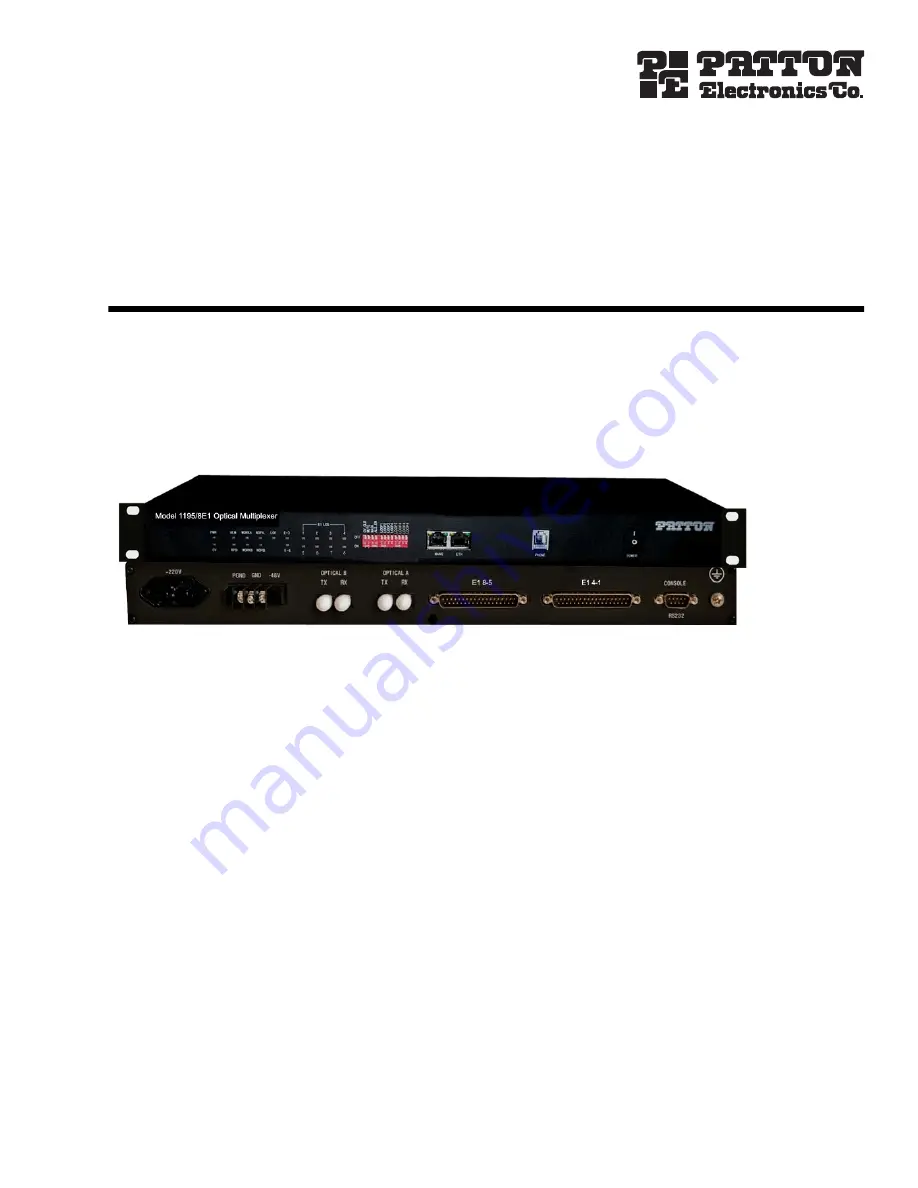
Model 1195/8E1
Optical Multiplexer


