background image


Model 2292/2294 Quick Start Guide


3


   2.


Installing the 10/100 Ethernet port cable or cables
(see 


1.4 “Installing the Ethernet cable” 


on page 5)


   3.


Installing the power input
(see 


1.5 “Connecting to external power source” 


on page 6)


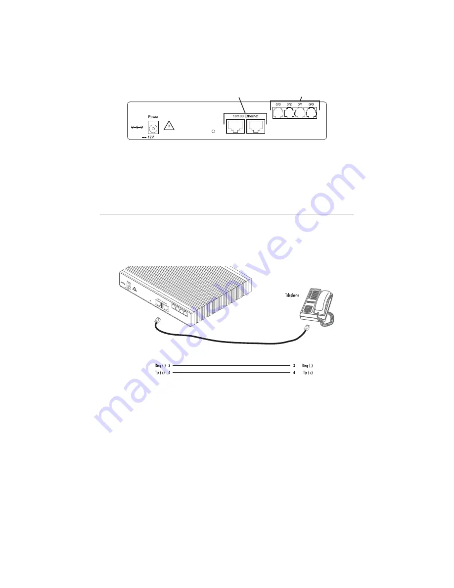
1.3  Installing an interface cable on the extender’s voice ports


The SmartNode extender comes with at least two voice ports (see 


figure 1


) located on the back of the extender. 

The voice ports are connected to analog devices via cables (see 


figure 2


 and 


figure 3


) terminated with RJ-11 con-

nectors (see 


figure 4


 and Table 1 on page 4 for pin-out information). 


Figure 1. 


Rear view showing location of Ethernet connectors and voice ports (SmartNode 2294 shown)


Figure 2. 


FXS connection

, 1.25A

Reset

Ports

ETH 0/1

ETH 0/0

Ethernet connectors

Voice ports

RJ-11, male

RJ-11, male

, 1.25A

Reset

Ports

ETH 0/1

ETH 0/0

Summary of Contents for SmartNode 2292

Page 1: ...and is intended for use in a light industrial environment It is not intended nor approved for use in an industrial or residential environment Part Number 07M2292 QS Rev A Revised April 13 2009 Sales O...

Page 2: ...The external power adapter shall be a listed Limited Power Source Ensure that the power cable used meets all applicable standards for the country in which it is to be installed and that it is connect...

Page 3: ...comes with at least two voice ports see figure 1 located on the back of the extender The voice ports are connected to analog devices via cables see figure 2 and figure 3 terminated with RJ 11 con nec...

Page 4: ...age TNV Table 1 RJ 11 socket Pin Signal 3 Ring 4 Tip RJ 11 male RJ 11 male PSTN wall plate 1 25A Reset Ports ETH 0 1 ETH 0 0 Socket 6 5 4 3 2 1 Plug 1 2 3 4 5 6 L in k 1 0 0 M A c ti v it y 0 0 0 1 0...

Page 5: ...ports see table 2 for port pin out listing via a cable terminated with RJ 45 plugs Because the SmartNode 2294 Series does not have the MDX feature a cross over cable is required when connecting Smart...

Page 6: ...n appropriate power outlet 4 Verify that the green Power LED is lit 2 0 Configuring the SmartNode extender Patton SmartNodes can be used for a wide variety of IP based network applications To support...

Page 7: ...twork 3 Load configuration Console port Serial interface PC or workstation with VT 100 emulation terminal Ethernet interface ETH0 PC or workstation or VT 100 emulation terminal 2 Modify configuration...

Page 8: ...m on the PC or workstation that supports the serial interface e g HyperTerm Figure 8 Connecting to the terminal Terminal emulation program settings 9600 baud no parity 8 bit 1 stop bit 1 start bit No...

Page 9: ...startup config Copy running config startup config 4 Follow the same procedure for the other SmartNode 229x device in the pair Copy nvram b side config startup config Copy running config startup confi...

Page 10: ...Warranty trademark compliance A 0 Customer and Technical Support Toll Free VoIP support call sip support patton com with a VoIP SIP client Online support www patton com E mail support support patton...

Page 11: ...cil Directive 1999 5 EC on the approximation of the laws of the member states relating to Radio and Telecommunication Terminal Equipment and the mutual recognition of their conformity The safety advic...

Page 12: ...s Company All other trademarks presented in this docu ment are the property of their respective owners Warranty For warranty information refer to the Model 2292 2294 Getting Started Guide located on t...

Reviews: