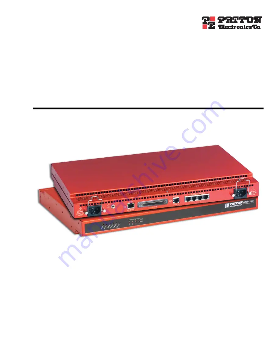
background image


Model 2960/2996


Remote Access Server (RAS)


Getting Started Guide


Sales Office:


+1 (301) 975-1000


Technical Support:


+1 (301) 975-1007


E-mail:


[email protected]


WWW:


www.patton.com


Document Number: 


2960-107081U Rev. G


Part Number: 


07MD2960-GS


Revised: 


January 13, 2010

Summary of Contents for NetLink 2960 RAS

Page 1: ...ess Server RAS Getting Started Guide Sales Office 1 301 975 1000 Technical Support 1 301 975 1007 E mail support patton com WWW www patton com Document Number 2960 107081U Rev G Part Number 07MD2960 G...

Page 2: ...m Copyright Copyright 2001 2010 Patton Electronics Company All rights reserved Notice The information in this document is subject to change without notice Patton Elec tronics assumes no liability for...

Page 3: ...96 Remote Access Server overview 14 Hardware overview 15 WAN 15 LAN 15 Signaling 16 Modems 16 RS 232 control port 16 Power system 16 Central processing unit 16 Temperature 16 Altitude 16 Humidity 16 P...

Page 4: ...ser 38 Configuring dial in user information 39 Configuring the default gateway 41 Configuring line settings and signaling for E1 42 Configuring the line settings 43 Setting the line signaling for an E...

Page 5: ...a saved configuration 62 Completing the installation 66 6 Contacting Patton for assistance 67 Introduction 68 Contact information 68 Warranty Service and Returned Merchandise Authorizations RMAs 68 Wa...

Page 6: ...Contents Model 2960 2996 RAS Getting Started Guide 6...

Page 7: ...s the company s inside wiring associated with a single line individual service may be extended by means of a certified connector assembly telephone extension cord The customer should be aware that com...

Page 8: ...red Universal Service Order Code USOC jack RJ 48C The make model number and FCC Registration number of the RAS 2 Your telephone company may make changes to its facilities equipment operations or proce...

Page 9: ...re is a LAN connected to the Ethernet port of the RAS Audience This guide is intended for the following users Operators Installers Maintenance technicians Structure This guide contains the following c...

Page 10: ...zard symbol and CAUTION heading indicate a potential electric shock hazard Strictly follow the instructions to avoid property damage caused by electric shock The alert symbol and CAUTION heading indic...

Page 11: ...se button unless you have changed the default configuration Point This word means to move the mouse in such a way that the tip of the pointing arrow on the screen ends up resting at the desired locati...

Page 12: ...About this guide Model 2960 2996 RAS Getting Started Guide 12...

Page 13: ...verview 14 Hardware overview 15 WAN 15 LAN 15 Signaling 16 Modems 16 RS 232 control port 16 Power system 16 Central processing unit 16 Temperature 16 Altitude 16 Humidity 16 Physical dimensions 17 Sec...

Page 14: ...10 100 Ethernet port IP Routing Frame Relay PPP forwarding and four T1 E1 WAN ports The 2960 2996 RAS simultaneously consolidates analog modem and digital ISDN remote access connections over PSTN dig...

Page 15: ...supplies with 32 to 72 VDC are available Figure 2 Model 2960 2996 RAS features Cool White version shown WAN The RAS includes four WAN ports each of which is software selectable for T1 E1 or PRI operat...

Page 16: ...inout A VT 100 console management interface Hardware CD and DTR signals for external modem support Power system Fixed internal dual redundant load sharing power supplies Universal input voltage range...

Page 17: ...al database of over 111 static users RADIUS Client supporting dual Authorization and Accounting servers Framed connections PPP PAP CHAP Unframed connections User name login and password Dual SNMP HTTP...

Page 18: ...ool management User configurable login prompts and banners Status reporting of all access server parameters Built in HTTP server for complete configuration and control using a standard Web browser Fig...

Page 19: ...te call activity on the Model 2960 2996 WAN STATUS Green indicates normal status at each of the four T1 E1 PRI links Red indicates an error Approvals The Model 2960 2996 RAS has achieved the following...

Page 20: ...cation 10 second average Online help 802 3 Ethernet ARP RARP IP over Ethernet Proxy ARP for dial up IP addresses PSTN Connectivity T1 CT1 Robbed Bit with Ground Start Loop Start E M Wink E M Immediate...

Page 21: ...23 Installing the power cables 23 Grounding the Model 2960 2996 24 Connecting the Ethernet ports 25 Connecting the 10 100Base T Ethernet port to an Ethernet switch or hub 25 Connecting the 10 100Base...

Page 22: ...Access Server RAS A DB 9 to RJ 45 EIA 561 cable 10 foot 3 meters Control port interface cable 10 foot 3 meters standard CAT 5 cable Two WAN connection cables 10 foot 3 meters each Rack mounting kit wi...

Page 23: ...e Figure 5 Attaching the cable retainer clip Installing the power cables This section describes installing the female end of the power cables into the IEC 320 connectors on the RAS Do not connect the...

Page 24: ...reach one of the following ground sources The building ground rod generally located at the site s main service entrance A sprinkler system pipe A cold water pipe Building structural steel 2 Install t...

Page 25: ...necting the RAS to the Ethernet LAN via an Ethernet hub switch or workstation Figure 8 Model 2960 2996 network and configuration ports Connecting the 10 100Base T Ethernet port to an Ethernet switch o...

Page 26: ...J 45 cable between the RAS RS 232 port see figure 8 on page 25 and an open serial port on your computer If you need to assemble your own cable refer to the pinout diagram in figure 11 Figure 11 DB 9 t...

Page 27: ...t where you can begin configuring the software settings 1 Verify that the AC power cord included with your RAS is compatible with local standards If it is not refer to Chapter 6 Contacting Patton for...

Page 28: ...2 Hardware installation Model 2960 2996 RAS Getting Started Guide 28 Completing the hardware installation...

Page 29: ...dial in user information 39 Configuring the default gateway 41 Configuring line settings and signaling for E1 42 Configuring the line settings 43 Setting the line signaling for an E1 PRI ISDN line 44...

Page 30: ...to the remote access server s local LAN The IP address and subnet mask for the RAS s Ethernet port A range of IP addresses to be assigned to the dial in users IP pool The IP addresses of the domain n...

Page 31: ...l 3 Set up HyperTerminal as follows Open a HyperTerminal session Enter a name for this connection Click on the Connect using pop up menu and choose the Direct to ComX option where X is the number of t...

Page 32: ...paring the RAS for configuration Figure 14 COM properties Figure 15 Terminal keys configuration Configure the Settings for Function arrow and ctrl keys act as to Terminal keys as shown in figure 15 4...

Page 33: ...elect option g Ethernet 7 Select a PrimaryIpAddress to set the Ethernet IP address 8 Type the IP address at the prompt then press RETURN 9 Use the left arrow key to return to the previous menu 10 Sele...

Page 34: ...ng the RAS with a Web browser This section describes configuring the following User authentication Dial in user configuration Default gateway Opening the RAS Web Administration Pages Do the following...

Page 35: ...gure 19 The Configuration Menu contains the links to the various RAS subsystems while the configuration information pane is where you can view status and other information or make changes to the syste...

Page 36: ...ons buttons Hard Reset this button figure 20 causes the RAS to perform a cold restart When you select Hard Reset the RAS confirms that you want to execute this command Then the RAS will disconnect all...

Page 37: ...wing sections describe two methods for configuring simple authentication to test the setup No Validation A No Validation authentication setting means that the user will be able to log in without requi...

Page 38: ...on to noValidation 0 4 Click on the Submit Query button A Static User The Static User authentication setting means that the user will have to use the static username and password you create to log in...

Page 39: ...lick on Modify The Authentication Configuration window appears see figure 22 on page 38 6 Change Validation to StaticUsers 1 7 Click on the Submit Query button Note Static Users or RADIUS are not used...

Page 40: ...he first and last host in the block for example 192 49 110 151 155 The addresses can be from a subnet other than the local network the RAS is on The IP address pool can have IP addresses from multiple...

Page 41: ...bles users to find locations on the Internet 7 Click on Submit Query Configuring the default gateway Do the following to add the default gateway if it was not already configured through HyperTerminal...

Page 42: ...on Menu The T1 E1 Link Activity window appears see figure 28 Figure 28 T1 E1 Link Activity window 2 Link 1 corresponds to Line 1 on the RAS This is the primary link for dial in callers Under Link 1 Cl...

Page 43: ...menu see figure 29 on page 42 and select e1pulse 1 4 Click on Yellow Alarm Format pop up menu see figure 29 on page 42 and choose from the following options For an E1 PRI line choose linkYellowFormatD...

Page 44: ...nal Mode pop up menu and choose messageOriented 4 3 Click on the Message Oriented Switch Type pop up menu see figure 31 and choose CTR4 3 4 Click on Submit Query Signaling is now configured for E1 PRI...

Page 45: ...ect from the phone company The called Number is the number a user dials to call into the RAS 9 Set the First Middle and Last Response Codes These are the codes the switch expects after each digit sent...

Page 46: ...Configuration Menu The T1 E1 Link Activity window appears see figure 28 on page 42 2 Click on Channel Assignment The WAN Circuit Channel Assignment window appears see figure 33 Figure 33 WAN Circuit...

Page 47: ...PRI line Otherwise refer to Setting the line signaling for a robbed bit T1 line Setting the line signaling for an ISDN PRI line Do the following 1 Scroll down the WAN Circuit Configuration window unti...

Page 48: ...s 4 Click on Submit Query Saving your configuration The basic configuration for the RAS is now finished Do the following to save your configuration settings 1 Select Home on the Configuration Menu The...

Page 49: ...the Configuration Menu to display the Import Export main window see figure 34 Figure 34 Import Export main window 5 To export the flash configuration click on the Export Flash link on the Import Expo...

Page 50: ...ion This section verifies that the RAS is fully operational 1 Temporarily disconnect the male ends of both power cords from the power outlet Wait 30 seconds then plug the power cords in again 2 Verify...

Page 51: ...RAS 10 100 Ethernet port a green LED that indicates line speed and a yellow LED that indicates link status and activity Verify that the yellow LED is either flashing yellow meaning that packets are b...

Page 52: ...3 Configuring the RAS for operation Model 2960 2996 RAS Getting Started Guide 52 Completing the installation...

Page 53: ...53 Chapter 4 Operation and shutdown Chapter contents Introduction 54 Activating the RAS 54 De activating the RAS 54...

Page 54: ...dicating that the RAS is satisfied with the quality of the T1 E1 PRI signal 4 After 10 seconds the Link A Error LED extinguishes indicating that the RAS is satisfied with the network signal and that t...

Page 55: ...s 57 Periodic maintenance 59 Calibration 59 Maintenance 59 Replacing the RAS 59 Exporting the current RAS configuration 59 Removing the defective RAS 61 Installing the replacement RAS 62 Verifying the...

Page 56: ...e 59 to replace the RAS CPU FAIL LED is lit CPU has failed As soon as possible unplug both power cables from the RAS wait 30 seconds then plug the cables back into the RAS to see if the problem disapp...

Page 57: ...fic time then refer to Replacing the RAS on page 59 to replace the RAS Off No input power is being applied Verify that power is being supplied to the RAS CPU FAIL Front panel Red On solid The CPU has...

Page 58: ...mended Flashing Indicates that the RAS is detecting the network but is unable to synchronize with it Off Indicates an error WAN PORT ERROR Front panel Red On solid Indicates signal from WAN is not pre...

Page 59: ...ration The Import Export function enables you to make a backup or export copy of your access server s configura tion parameters By exporting the configurations the saved files can quickly be loaded or...

Page 60: ...perating parameters To ensure that you export the most current parameters go to HOME then click on the Record Current Configuration button under Immediate Actions 3 To export the flash configuration c...

Page 61: ...file Removing the defective RAS 1 Remove the replacement RAS from its shipping container and place it near where the malfunctioning RAS is located 2 Unplug both male power cable connectors from their...

Page 62: ...able 7 Install the power cable into their IEC 320 connectors 8 Rotate the power cable retainer clips so they secure the power cable plugs in the IEC 320 connectors Verifying the hardware installation...

Page 63: ...Terminal session Enter a name for this connection Click on the Connect using pop up menu and choose the Direct to ComX option where X is the number of the COM port onto which you connected the cable i...

Page 64: ...etting Started Guide 64 Maintenance Configure the Settings for Function arrow and ctrl keys act as to Terminal keys as shown in figure 42 Figure 42 Terminal keys configuration 4 Press RETURN to displa...

Page 65: ...14 Select 1 StoreConfig to save your IP address and netmask The RAS is now prepared for configuration using a Web browser 15 To import a saved configuration connect your Web browser to the Administrat...

Page 66: ...he Link 1 Frame LED illuminates indicating that the RAS is synchronizing with the T1 E1 PRI signal 4 Verify that after 5 seconds the Link A Error LED begins flashing indicating that the RAS is satisfi...

Page 67: ...r contents Introduction 68 Contact information 68 Warranty Service and Returned Merchandise Authorizations RMAs 68 Warranty coverage 68 Out of warranty service 68 Returns for credit 68 Return for cred...

Page 68: ...efore ship ment All of our products are backed by a comprehensive warranty program Note If you purchased your equipment from a Patton Electronics reseller ask your reseller how you should proceed with...

Page 69: ...ing a request on the RMA Request page in the Support section at www patton com By calling 1 301 975 1000 and speaking to a Technical Support Engineer By sending an e mail to returns patton com All ret...

Reviews: