


3.1.2 Connecting to a “DTE” Device
The serial port on most interface modules (all except the X.21
module) is hard-wired as a DCE. Therefore these modules “want” to
plug into a DTE such as a terminal, PC or host. When making the
connection to your DTE device, use a straight through cable of the
shortest possible length—we recommend 6 feet or less. When pur-
chasing or constructing an interface cable, please refer to the pin dia-
grams in Appendix C as a guide.
3.1.3 Connecting to a “DCE” Device
If the Model 1095RC interface module is hard-wired as a DCE (all
except the X.21 module), you must use a
null modem cable when con-
necting to a modem, multiplexer or other DCE device. This cable
should be of the shortest possible length—we recommend 6 feet or
less. When purchasing or constructing a null modem interface cable,
use the pin diagrams in Appendix C as a guide.
3.1.4 Configuring the X.21 Interface Module IM2RC/D
The serial port on the X.21 Interface Module is default wired as a
DCE, but may be switched to a DTE. This is done by reversing the ori-
entation of the DCE/DTE strap, as described below:
To reverse DCE/DTE orientation, remove the interface module
according to the instructions in Section 3.1.1. The DCE/DTE strap is
located on the top side of the interface module’s PC board. The
arrows on the top of the strap indicate the configuration of the X.21
port (for example, if the DCE arrows are pointing toward the rear card
connector, the X.21 port is wired as a DCE). Reverse the DCE/DTE
orientation by pulling the strap out of its socket, rotating it 180º, then
plugging the strap back into the socket. You will see that the
DCE/DTE arrows now point in the opposite directions, showing the
new configuration of the X.21 port. Reinstall the module according to
the instructions in Section 3.1.1.
7
NOTE:
Pin-out requirements for null modem applications vary
widely between manufacturers. If you have any questions about
a specific application, contact Patton Electronics Technical
Support.
3.1.5 Configuration DIP Switch Set “S1” - Management Address
Switch S1 is used to set the address of the card in the NetLink
Network Management System. When the 1095Rc is installed with a
Model 1001MC, the cards and their remote units can be SNMP man-
aged using a standard Network Management Station (NMS) or a stan-
dard web browser (Netscape, Internet Explorer). For more information
about setting the address, refer to Appendix a of the Model 1001
Operations Manual.
NOTE: If you are not using your Model 1095RC in a Network
Managed environment, please set all Switch Set S1 switches
to the ON position
3.1.6 Configuration DIP Switch Set “S2”
The configuration switches on S2 allow you to specify the Line
Rate, Clocking Mode and response to DTE Loop Enable. Default set-
tings of S2 are shown in the table below.
Switches S2-1, S2-2, S2-3, S2-4, S2-5: Reserved for Future Use
and Should Remain in the Off Position.
8
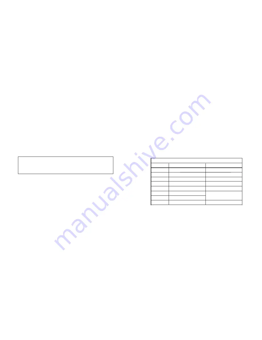
S2 SUMMARY TABLE
Function
Factory Default
Position
Reserved
Off
S2-1
Reserved
Off
S2-2
Reserved
Off
S2-3
Reserved
Off
S2-4
Reserved
Off
On
On
S2-5
Enable Loop from DTE
Off Disable
S2-8
Clock Mode
S2-6
Clock Mode
S2-7
Internal
}