Patton electronics Kilolight 1184, User Manual
The Patton Electronics Kilolight 1184 is a versatile and reliable networking device. Ensure optimal performance by referring to the included User Manual. Download your free manual from manualshive.com to learn how to maximize the capabilities of your Kilolight 1184 and troubleshoot any issues effectively.
Share
Download


Reviews:
No comments
Related manuals for Kilolight 1184

Hybrid
Brand: Falcon Pages: 36

RAy3
Brand: RACOM Pages: 19

TM02AA104
Brand: Arris Pages: 52

CHITA
Brand: Hitron Pages: 2

SAMBA 75
Brand: FALCOM Pages: 31

ODW-730-F2
Brand: Westermo Pages: 21
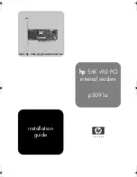
p5091a
Brand: HP Pages: 14

J8135A
Brand: HP Pages: 30

D7808A
Brand: HP Pages: 50

USR-G760c
Brand: USR IOT Pages: 37

USR-GPRS232-730
Brand: USR IOT Pages: 45

USR-G786-G
Brand: USR IOT Pages: 66

RB IndustrialRT
Brand: Teleorigin Pages: 13

433NW30
Brand: Ebyte Pages: 18

433C33
Brand: Ebyte Pages: 18

433L20
Brand: Ebyte Pages: 18

900SL30-ETH
Brand: Ebyte Pages: 24

Proxima ISDN Lite
Brand: Bausch Datacom Pages: 64


