GB
- 82 -
4. Technical data
Idle speed n
0
....................................12,000 min
-1
Air speed ...............................................210 km/h
Max. operating time ..................... approx. 20 min
Protection class: ................................................III
L
WA
sound power level .............................79,5 dB
L
pA
sound pressure level ..........................68,5 dB
K uncertainty ................................................3 dB
Interchangeable battery ......18 V d.c. / 3000 mAh
.............................(optional 18 V d.c. / 1500 mAh)
Vibration a
hv
.........................................
≤
2.5 m/s
2
K uncertainty ...........................................1.5 m/s
2
Weight: .......................................................1.5 kg
Charging unit
Mains voltage ................... 220-260 V ~ 50-60 Hz
Output
Rated voltage: ........................................ 21 V DC
Rated current ....................................... 3,000 mA
The machine may exceed 85 dB (A). The operator
will require noise protection measures if this is
the case.
The speci
fi
ed vibration value was established in
accordance with a standardized testing method. It
may change according to how the electric equip-
ment is used and may exceed the speci
fi
ed value
in exceptional circumstances.
The speci
fi
ed vibration value can be used for initi-
al assessment of a harmful e
ff
ect.
Important!
The vibration value changes according to the
area of application of the electric equipment and
may exceed the speci
fi
ed value in exceptional
circumstances.
Keep the noise emissions and vibrations to a
minimum.
•
Only use appliances which are in perfect wor-
king order.
•
Service and clean the appliance regularly.
•
Adapt your working style to suit the appliance.
•
Do not overload the appliance.
•
Have the appliance serviced whenever ne-
cessary.
•
Switch the appliance off when it is not in use.
•
Wear protective gloves.
5. Before starting the equipment
5.1 Fitting the blower tube (Fig. 3)
Plug the blower tube (Fig. 1) to the motor unit
(Item 3).
5.2 Fitting the battery pack (Fig. 4a/4b)
Press the pushlock button of the battery pack as
shown in Fig. 4a and push the battery pack into
the mount provided. When the battery pack is po-
sitioned as in Fig. 4b, make sure that the pushlock
button latches in place! To remove the battery
pack, proceed in reverse order.
5.3 Charging the battery (Fig. 5)
1. Take the battery pack out of the equipment.
Do this by pressing the side pushlock buttons.
2. Check that your mains voltage is the same as
that marked on the rating plate of the battery
charger. Insert the power plug of the charger
(4) into the mains socket outlet. The green
LED will then begin to
fl
ash.
3. Insert the battery pack (5) into the battery
charger (4).
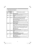
4. In the section entitled „Charger indicator“ you
will
fi
nd a table with an explanation of the LED
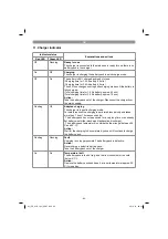
indicator on the charger.
The battery pack can become a little warm during
the charging. This is normal.
If the battery pack fails to charge, check:
•
whether there is voltage at the socket outlet
•
whether there is good contact at the charging
contacts
If the battery pack still fails to charge, take
•
the charging unit
•
and the battery pack
to your Hornbach store.
Anl_PE_ALB_18_Li_SPK7.indb 82
Anl_PE_ALB_18_Li_SPK7.indb 82
20.10.14 08:00
20.10.14 08:00
Summary of Contents for PE-ALB 18 Li
Page 89: ...89 Anl_PE_ALB_18_Li_SPK7 indb 89 Anl_PE_ALB_18_Li_SPK7 indb 89 20 10 14 08 00 20 10 14 08 00...
Page 90: ...90 Anl_PE_ALB_18_Li_SPK7 indb 90 Anl_PE_ALB_18_Li_SPK7 indb 90 20 10 14 08 00 20 10 14 08 00...
Page 91: ...91 Anl_PE_ALB_18_Li_SPK7 indb 91 Anl_PE_ALB_18_Li_SPK7 indb 91 20 10 14 08 01 20 10 14 08 01...

