
P-K Storm
TM
Gas Fired Boiler
Technical Service 1.877.728.5351
Revised: June 26, 2020
Released: June 26, 2020
©
Patterson-Kelley 2020
All Rights Reserved.
2691000273 P-K Storm ST2500-ST4000
Installation and Owners Manual Rev A.docx
Page 90
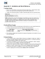
Appendix E
– Installation and Quick Reference
Fuel/Gas Supply
•
Refer to
for information on proper sizing of the gas supply piping. Undersized gas piping
with too much pressure drop will negatively impact the boiler’s performance.
•
Install a lock-up type gas regulator to supply an appropriate gas pressure as described below:
Natural Gas
Minimum Inlet Pressure = 4
.0”
W.C
.
Maximum Inlet Pressure = 14.0”
W.C.
NOTE:
Patterson-Kelley recommends installing an individual lock-up type gas regulator in the
gas supply piping to each boiler. For installations where one master lock-up type gas pressure
regulator will service multiple boilers, Patterson-Kelley recommends contacting the local
regulator representative for application assistance specifying the appropriate lock-up type
regulator and gas pipe sizing.
Electrical/Power Supply
•
Carefully inspect the boiler’s nameplate labels which describe the power supply requirements.
•
Provide an appropriate power feed to the boiler with overcurrent protection:
Boiler Model
Power Supply Requirements
ST-2500, ST-3000,
ST-3500, ST-4000
208-240VAC/440-480,
three phase
, 60Hz sized for 20
Amps.
•
Prior to startup, carefully check all electrical connections for tightness as connections can come
lose during shipping.
Exhaust Venting
•
The
P-K STORM
boilers are dual-certified as Category II & Category IV appliances, capable of
operating with slightly negative to slightly positive exhaust pressure. It is critical to ensure the
flue venting material is suitable for use with the boiler.
•
For Category II installations, ensure the flue venting system is designed to maintain a slightly
negative exhaust pressure
between -
0.01” W.C. and -0.05” W.C.
•
For Direct Vent / Sealed Combustion Category IV installations, ensure the flue venting system is
designed to maintain a slightly positive exhaust pressure
b0.01” and +0.22” W.C.
•
For Exhaust Only Category IV installations, ensure the flue venting system is designed to
maintain a slightly positive exhaust pressure
betwee
n +0.01” and +0.4” W.C.