P-K Storm
TM
Gas Fired Boiler
Technical Service 1.877.728.5351
Revised: June 26, 2020
Released: June 26, 2020
©
Patterson-Kelley 2020
All Rights Reserved.
2691000273 P-K Storm ST2500-ST4000
Installation and Owners Manual Rev A.docx
Page 62
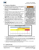
5.4 Sequence of Operations
1. When the Boiler On/Off switch is turned on, power is provided
through over-current protection (fuse and/or circuit breaker) to
the boiler control and the combustion blower.
2. When the outlet
water temperature drops below “
CH
SETPOINT
” minus “
CH DIFFERENTIAL ON
”, a heat request
is generated.
3. Provided all interlocks are made and the remote enable signal
(if installed) is active, the boiler will attempt to start.
4. The NURO control checks to make sure air pressure switch is
open indicating there is no airflow through the boiler. The
combustion blower is then driven towards the pre-start fan
speed. When the air pressure switch closes, the “
PRE
PURGE TIME
” timer is started. Once the “
PRE PURGE
TIME
” timer expires, the blower is driven to the ignition speed.
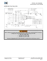
5. A trial for ignition begins and the sequence of events is
illustrated graphically below. A valid flame signal must be
detected within 4 seconds after the gas valves open (elapsed
time 7 seconds).
6. After a successful ignition, the fan is driven to low fire and the
“
CH LOW FIRE HOLD TIME
” timer is started. Once the
“LOW FIRE HOLD TIME” timer expires, the boiler is released
to modulation.
7. The NURO Control modulates the firing rate between low and high fire to maintain the desired
outlet water temperature.
8.
The burner will continue firing until the outlet water temperature exceeds “
CH SETPOINT
” plus
“
CH DIFFERENTIAL OFF
”. At this temperature, the gas valves are closed combustion air fan
contin
ues to run until the “
POST PURGE TIME
” timer has expired.
9. When the outlet water temperature is reduced by the load on the system, a heat request is
generated. The operating sequence will recycle to
Step 3
.
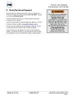
5.5 Troubleshooting
The NURO control will display graphical and/or text based error descriptions to announce any problems
with the boiler. There are two types of lockouts: manual reset lockouts which require the operator to
If any “Manual Reset” limit device
trips, DO NOT reset without
determining and correcting the
cause. Manual Reset Limits
include: Flame safeguard, high or
low gas pressure, high
temperature limit, stack
temperature, low water level.
Attempting to operate a boiler
without diagnosing the cause of
failure can result in unsafe
operation, increasing the risk of
injury. Never attempt to bypass a
safety limit device.
N
OTICE
!
Once the boiler begins the
ignition sequence, the firing
sequence will continue until
main flame is reached
regardless of heat request. The
sequence can be interrupted by
turning the power switch off.

