MACH® Series
Gas-Fired Boiler
Installation
Page 14
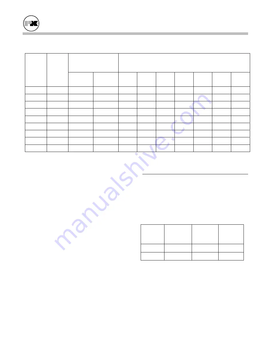
Pipe Capacity for Natural Gas
Equivalent Pipe Length
Maximum Capacity in Cubic Feet of Natural Gas per Hour
Pressure Drop of 0.5 inch Water Column/Equivalent Length of Pipe
(in feet)
Nominal
Iron Pipe
Size
(Inches)
Internal
Diameter
(Inches)
90º Ell
(Feet)
Tee
(Feet)
20
40
60
80
100
150
200
1/2 0.622 1.55
3.1 120 82 66 57 50 40 35
3/4 0.824 2.06
4.12 250 170 138 118 103 84 72
1 1.049 2.62
5.24 465 320 260 220 195 160 135
1- 1/4
1.380
3.45
6.9
950 660 530 460 400 325 280
1- 1/2
1.610
4.02
8.04 1460 990 810 690 620 500 430
2
2.067
5.17
10.3
2750 1900 1520 1300 1150 950 800
2- 1/2
2.469
6.16
12.3
4350
3000 2400 2050 1850 1500 1280
3
3.068
7.67
15.3
7700 5300 4300 3700 3250 2650 2280
4
4.026
10.1
20.2 15800
10900 8800 7500 6700 5500 4600
3.7.1 Gas Supply Piping by Installer
The boiler and all gas piping connections should be
pressure-tested and must be checked for leaks before
being placed into service. Test with compressed air or
inert gas if possible.
The boiler must be
disconnected
at the boiler manual
shut-off valve (located at the end of the supplied gas
train) from the gas supply piping system during any
pressure testing of the system at pressures in excess of
1/2 psig (14" W.C.).
During any pressure testing of the gas supply piping
system at pressures equal to or less than 1/2 psig (14"
W.C.), the boiler should be isolated from the gas
supply piping system by closing the manual shut-off.
Some leak test solutions, including soap and water,
may cause corrosion. These solutions should be
rinsed-off with water after testing.
3.8
B
OILER
W
ATER
P
IPING
3.8.1 Piping Design
Water Flow in System
For proper water flow requirements see below.
Incorrect flow may result in eventual damage or
premature failure of the equipment.
Model Max
Flow
GPM for
20ºF
Δ
T
Min Flow
GPM for
40ºF
Δ
T
DP ft. at
max flow
2000 188 94 17.5
1500 141 70 20
Contact factory for minimum flow at other than
maximum firing rate.


