


The low backlash is achieved with a variable pitch worm. The width of the worm tooth slowly increases
along the worm. Since only one small portion of the worm tooth is meshing with the worm gear, by
moving the worm axially, you can vary which section / width of the worm tooth is being used to drive
the worm gear. Therefore the backlash can always be minimized to 1-3-arc minutes. (Figure 3.2)
The gearbox contains synthetic oil filled half way to the level plugs. Because of the design capacity of
the gearbox, low rpm and comparative limited cycles experienced by an SNG system, no wear or
maintenance is expected. If azimuth backlash of the positioner ever exceeds 0.020°, it may be
brought back to 0.005° factory setting by adjusting backlash in gearbox. (Figure 3.2).
Figure 3.2
3.4 AZIMUTH CABLE DRIVE
The azimuth drive produces a near-zero backlash, high stiffness, low-wear, no lubrication, maximum
reliability drive system. The system consists of four 3/32, 9 x 17 stainless steel aircraft control cables
reverse wrapped twice around the grooved capstan with solid connections on one end and high force,
belleville springs on the other end occurring at the azimuth spring block. One cable has the capacity to
withstand the 80-mph wind load. The additional cables are used to provided increased stiffness and
drive redundancy.
If a cable becomes damaged during usage, merely cut off cable and continu
to use positioner. The cable can be replaced whenever time permits at a typical maintenanc
facility.
The cables are sized to last the life of the positioner. No replacement from wear is expected. The
spring’s package at one end will automatically compensate for any elongation of the cable. (Figure
3.3)
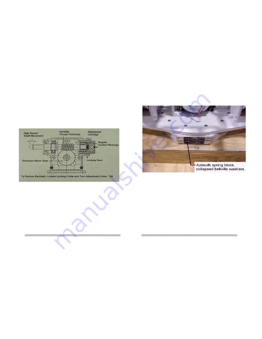
Figure 3.3
Since all systems seek the condition of lowest potential energy, the cables after an adequate time for
break in will eventually stop stretching. At installation the belleville springs are collapsed until no “air”
is seen between the springs. You should check this condition yearly to account for the slow settling of
the cable strands. Use a 3/16 open wrench or pliers to hold the stud and 7/16 box end wrench to
tighten nut.
Be sure not to over tighten the cables, but the belleville springs should almost be
fully collapsed.
(See Figure 3.3)
3.5 AZIMUTH POSITION FEEDBACK
The azimuth position feedback is produced by a 10 turn, 1K ohm potentiometer driven by the output
shaft of the worm gear box. Since the drive has nearly no backlash, the position feedback is as
accurate as the resolution and accuracy of the potentiometer and the backlash between the
potentiometer and the output shaft of the worm gear box. The potentiometer is rated for IP 65
environment – wind, rain, dust, etc. (See Figure 3.1 and 3.4)
12
13


