


Have personnel on both sides of truck observing orientation of gas strut U-joints. Watch reflector
surface approach feed horn.
STOP WHEN REFLECTOR GETS WITHIN 6 INCHES OF FEED HORN.
NOTE:
Elevation display has been disabled because electronic inclinometer produces erroneous
information at these angles.
Adjust stow switch adjustment screw in small increments until stow indication occurs at controller
when reflector surface is approximately 1” from padded reflector support.
Check that padded rest
screws are tight.
Raise in elevation approximately 10°, change speed to fast, and run down.
Keep finger on STOP
button!
Motors will stop when switch is actuated but the reflector will coast very slightly.
Continue to adjust stow limit actuation until reflector is preloaded against padded support and clearing
feed horn by at least ½”. The feed boom should be depressing roof very slightly. The padded rest may
be adjusted in height if necessary.
Raise reflector 30-45°, and observe in full stow mode by pressing STOW, BACKSPACE.
Retighten cradle screws.
A roll-pin pilot hole is provided for pinning the cradle if desired.
Reinstall elevation limit switch cover.
2.6 FINAL CALIBRATION
OF SYSTEM
If feed / reflector is not stowed centered on truck roof, the azimuth stow switch may be adjusted to
center on roof. Stow with positioner having to approach stow from both directions. See Section 3.6 if
azimuth stow position needs adjusting. If azimuth readout is not zero + / -2° when azimuth antenna is
stowed adjust zero voltage per Section 4.1.1 of controller manual.
2.7 LNA/LNB INSTALLATION
Install LNB/LNA’s to the ports in the feed boom housing.
Due to the fact that stow switch actuation occurs at slightly different positions depending on the
direction of approach, clockwise or counterclockwise, the azimuth stow may vary approximately 1°
from the actual 0° heading.
The mount has the mechanical capability of 270°. However, the limits must be set at +120° per section
4.1.2 of controller manual to prevent damage to the azimuth rotary joints on a 4-port system.
4.0 ELEVATION POSITIONING SYSTEM
The elevation pivot assembly consists of two elevation drum assemblies pivoting between two clevis
blades that house the precision aircraft torque tube bearings. These bearings are precision ground
with lifetime seals. They are permanently lubricated with synthetic grease. No wear or maintenance is
expected.
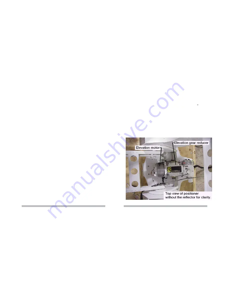
4.1 ELEVATION GEAR BOX
The elevation gearbox is a patented low backlash worm gear box. The worm gear drive isolates
backlash in the motor drive from the system. Also, since it is a 40:1 ratio it will not backdrive
eliminating any need for a brake on the drive train. (Figure 4.1)
Figure 4.1
10
15


