background image

This product includes the following option parts. For details, refer to our company website.

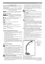
Make the necessary holes according to the product model and
installation method. (For more details on installation, refer to P.19)

Cut-out before use. 

M12 connector wiring hole 
(

ȭ

18)

Lead wire wiring hole 
(

ȭ

18)

Installation hole 
(

ȭ

5)

Installation hole 
(

ȭ

5)

Installation hole (

ȭ

5)

Spare installation hole 
(

ȭ

5)

Spare installation hole 
(

ȭ

5)

Product diameter

40

Nameplate position

(For models without Buzzer installed)

120°

120°

The diagram is of actual size. (Units: mm)

43

34.6

Nameplate position

(For      Buzzer installed models)

B

Front of product


(Buzzer Direction  )

B

For models with the       Buzzer installed

27

Platform Bracket

M12 Connector with Cable

(Lengths : 2m . 5m . 10m)

Wall-mount Bracket

Multi-mount Bracket

(Note) When mounting the option parts, refer to the operation manual included with it. 
           ("M12 Connector with Cable" not applicable)

Option Parts

14

LS7 Installation

Template

20

10

PIN No.

White

Color of Wire

Brown

Green

Yellow

Gray

Pink

Blue

Red

Summary of Contents for LS7

Page 1: ...2 3 3 4 5 7 9 10 12 13 12 10 11 4 B95100441 H LED 1 2 3 4 5 6 7 8 9 10 12 13 14 11 Model L S 7...

Page 2: ...OK P 10 B FA Factory Automation LED B 10 2 1...

Page 3: ...2 20 W LED R Y G B C 5 N DC24V C H M12 F B LS7 502WC RYGBC M12 LED LED LS7 302SFBWH RYGNN mm B H M12 C M12 2 H F 2 1 3 M4 3 1 P 13 M12 B 55mm 14 9 P 10 3 O A 1200 70 244 25 284 23mm LED 2 5 M4 3 1 3 O...

Page 4: ...1 2 P 13 B LED L E D L E D L E D L E D L E D DC24V LS7 F B LED LED 1 4 14 5 4...

Page 5: ...2 3 1 Type1 Enclosure O Type1 Enclosure UL P 13 P 13 B B 5 6...

Page 6: ...4 1 2 5 6 3 5 5 4 2 9 1 4 N m M4 2 M4 M12 P 4 P 9 B B C H P 4 mm 4 4 8 6...

Page 7: ...1 2 1mA A V 1 2 1 PLC 1mA LED LED LED ON OFF ON OFF ON OFF F F B B 7 7...

Page 8: ...ED LED LED LED LED LS7 LS7 LED LED LED LED LED 1 1A DC 24V PLC NPN LED LED LED LED LED 1 1A DC 24V PLC N N P LED PIN No M12 LS7 502 B W M12 PIN C H B B P 13 14 B B B B LS7 PLC PNP LED LED LED LED LED...

Page 9: ...LS7 DC 24V 1A LED LED LED LED LED 1 2 LS7 502 FBWH F B PLC 9 P 4 4 8 LS7 LED LED LED LED LED 1 2 PLC 1A DC 24V PLC PNP P P N LS7 LED LED LED LED LED 1 2 N N P PLC 1A DC 24V PLC NPN...

Page 10: ...2 3 1 LED P 11 P 11 P 12 P 4 M12 C B 4 11 11 13 10 10 9...

Page 11: ...LED P 3 P 8 9 DC24V LED P 8 9 DC24V P 8 9 LED P 4 B 1 2 1 F 7 P 8 9 LED 2 1 No 7 P 9 8 7 1 ON ON P 8 9 7 7 4 2 11 1 2 3 4 5 6 7 11...

Page 12: ...02 D S WC LS7 02 D S WH LS7 02 D S BWC LS7 02 D S FBWH LS7 02 D S WH LS7 02 D S BWC LS7 02 D S FBWH 60 12 260g 280g 320g 370g 82dB 1 82dB 2 85dB 150mA 520msec 40mA 30mA 10mA DC 24V 60 UL1007 AWG22 1...

Page 13: ...SZ 100 SZ 100D SZ 100S SZ 110 SZ 110D SZ 110S SZ 130 SZ 130D SZ 130S HP SZ 120 02 SZ 120 05 SZ 120 10 2m 5m 10m P 5 M12 18 18 5 5 5 5 5 40 1 2 0 1 2 0 mm 43 34 6 20 B B 13 10 14 LS7 PIN No PIN No...

Page 14: ...14 4 4 25 Ver 2 0...

Page 15: ...of this manual 16 17 17 18 19 21 23 24 26 27 26 24 25 18 Notice to Customer Read this manual carefully prior to installation Be sure to return this manual to the customer Notice to Contractor Page LE...

Page 16: ...long exposure to the buzzer sound from a close distance Failure to observe this may lead from irritation to permanent damage to the ears Buzzer included specifications Do not use the signal light as l...

Page 17: ...the Lead wires specifications H F 17 Base Mount O ring B M4 Bolts x3 Lead wires wire length 1200 Waterproof Packing Underside View Underside View Buzzer Case Buzzer Horn 244 25 284 Outer Cover Cap Inn...

Page 18: ...he buzzer The lock may be stiff When reinstalling fully rotate the base until the triangle mark and bar mark are aligned Hold the base and the mount and rotate until the bar marks are aligned Do not t...

Page 19: ...nd direction Buzzer included specifications Use a soft cloth etc dampened with water to wipe the main signal light unit Do not use cleaners containing chemicals such as thinner alcohol gasoline or oil...

Page 20: ...n unit Refer to Stackable Tower Construction P 18 for details on how to remove the mount Be careful not to pinch the lead wires or cable Adjust the sound to the desired level Refer to Volume Adjustmen...

Page 21: ...e Do not push lead wires up into the main unit Never connect the power supply wire to the flashing common wire Failure to observe will result in damage to the circuitry Illumination and flashing speci...

Page 22: ...nction Lead wire color Lead wires specifications PIN No M12 connector specifications LS7 502 B W Product specifications Model Refer to the M12 Connector Pin Layout illustration to the right C H Illumi...

Page 23: ...Wire Brown Buzzer 2 Sky blue Gray Red LED Amber LED Green LED Blue LED White LED Buzzer 1 Red Orange Green Blue White Power Supply Wire Power Supply Wire Yellow 23 No polarity The volume is set at max...

Page 24: ...P 25 if they do not illuminate If there is any external damage such as cracks or missing parts stop using the signal light and replace the necessary parts or the main unit Refer to Replacement Parts...

Page 25: ...ignal lights with a in the model type are equipped with a buzzer function The buzzer does not sound Is the wiring properly connected Refer to Wiring P 22 23 to double check the wiring connection Doubl...

Page 26: ...BWC LS7 02 None D S FBWH 60 12 times min Approx 260g Approx 280g Approx 320g Approx 370g Approx 82dB Buzzer 1 Approx 82dB Buzzer 2 Approx 85dB Inrush Current Buzzer Duration Wire Type Wire Gauge Indo...

Page 27: ...e 5 Product diameter 40 Nameplate position For models without Buzzer installed 1 2 0 1 2 0 The diagram is of actual size Units mm 43 34 6 Nameplate position For Buzzer installed models B Front of prod...

Page 28: ...ration All Rights Reserved Installation template Do not write here http www patlite co jp PATLITE Note Dimensions specifications and structure are subject to change for improvement without notice PATL...

Reviews: