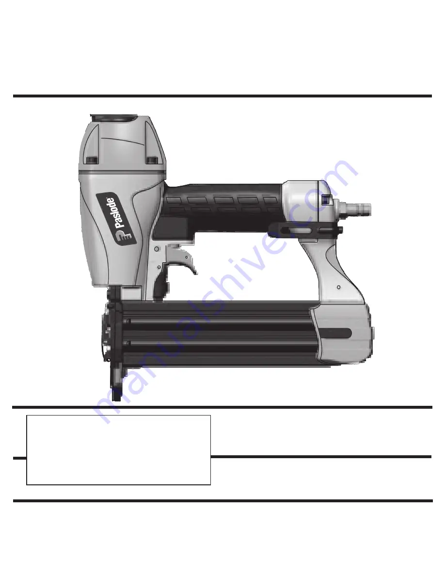
background image

MODEL T200-F18P

   18 Ga. Brad Nailer

IMPORTANT!

DO NOT DESTROY

It is the customerʼs responsibility to have all

operators and service personnel read and

understand this manual.

OPERATING MANUAL AND

SCHEMATIC

P

Part# 515600

515610-2

   08/17


PRINTED IN U.S.A.

© 2017, Illinois Tool Works Inc.

Summary of Contents for T200-F18P

Page 1: ...ORTANT DO NOT DESTROY It is the customerʼs responsibility to have all operators and service personnel read and understand this manual OPERATING MANUAL AND SCHEMATIC P Part 515600 515610 2 08 17 PRINTED IN U S A 2017 Illinois Tool Works Inc ...

Page 2: ...ing that was provided with your tool Paslode s sole liability hereunder will be to replace any part or accessory which proves to be defective within the specific time period Any replacement part or accessory provided in accordance with this warranty will carry a warranty for the balance of the period of warranty applicable to the part it replaces This warranty does not apply to part replacement re...

Page 3: ...is tool uses a 1 4 N P T male plug The inside diameter should be 28 7mm or larger The fitting must be capable of discharging tool air pressure when disconnected from the air supply OPERATING AIR PRESSURE 80 to120 psi Select the operating air pressure within this range for best tool performance DO NOT EXCEED THIS RECOMMENDED OPERATING PRESSURE TOOL AND FASTENER SPECIFICATIONS 3 ...

Page 4: ...ting element Do not use the tool unless the work contacting element is working properly The tool could fire unexpectedly DISCONNECT THE TOOL WHEN NOT IN USE Always disconnect the tool from the air line when it is not in use when you leave the work area or when moving the tool to a new location The tool must never be left unattended because people who are not familiar with the tool might handle it a...

Page 5: ...th the point of the fastener facing down and place the point of the fastener into the bottom of the magazine channel Placing fasteners on the top of the magazine will cause jamming Step No 3 Push the magazine firmly towards the front of the tool until it locks in place Connect the air supply The tool is now ready to use INSTRUCTIONS FOR LOADING 5 orange magazine release button at the Press release...

Page 6: ...from the work surface TOOL OPERATION continued Use only fasteners that meet Paslode specifications Use of fasteners that do not meet Paslode specifica tions can result in damage to the tool or injury to the operator or bystanders WARNING Precision Placement Driving Orange Trigger Grasp the tool handle firmly and hold the bottom of the work contacting element firmly against the workpiece until it is ...

Page 7: ...in the tank will keep the air free of frost Testing the Tool After Servicing After replacing any part or parts it is important to check the tool for proper operation This ensures that the tool was put together correctly is safe to use and will perform the job properly Ensure that all hardware is tight Ensure that the work contacting element is installed correctly in relation to the trigger and tha...

Page 8: ... from its air source Remove all fasteners Unlatch the front guide and lift open Remove jammed fastener and relatch front guide Reload fasteners close and latch the magazine Reconnect the air Changing the work contact element Operation Continued Disconnect tool from its air source ...

Page 9: ...0 psi CAUTION Disconnect the tool when performing repairs or clearing jams MAINTENANCE Add several drops of pneumatic oil into the air fitting Check that all screws on tool are tight Keep work contacting elelment working properly Keep magazine and feeder mechanism clean Lubricate O rings that are replaced Use only Paslode replacement parts W O H Y H W N O I T C A Keep tool lubricated Prevent air l...

Page 10: ...l 63 576935 1 Work Contact B 64 576936 1 Support 65 617540 1 Screw 66 617541 1 Pin 67 68 576937 1 69 576938 1 End Cap 70 576939 1 Belt Hook 19 576914 1 Piston Assembly 72 617534 1 Guide Spring 73 576940 1 Screw 74 60 617496 1 Rail 23 617508 Denotes Normal Wear Items Make sure Warning Label Part No 515620 is properly affixed Replace if necessary Apply Loctite 242 Blue Part No 093500 Denotes New Chan...

Page 11: ... 12 13 14 15 16 19 20 21 22 23 24 25 69 70 71 72 40 73 68 67 66 65 40 64 63 37 36 38 61 60 39 40 41 42 44 43 50 45 46 47 48 49 51 52 53 58 54 55 56 57 26 27 28 29 30 31 32 33 34 35 17 18 59 74 62 A B T200 F18P BRAD NAILER 515600 ...

Page 12: ...a P l l a r o f r e n a e l c l a e d I Safety Glasses 382 1 0 4 o N t r a P r a e l C ACCESSORIES An Illinois Tool Works Company 155 Harlem Avenue Glenview IL 60025 2017 Illinois Tool Works Inc Tool Case Handy carrying case that conveniently stores your tool 515615 o N t r a P s e i r o s s e c c a l a n o i t i d d a r o f m o o r h t i w Work Contact Element A B 576928 o N t r a P 576935 o N t ...

Page 13: ... herramientas Paslode 12 PRINTED IN U S A 2017 Illinois Tool Works Inc P An Illinois Tool Works Company 155 Harlem Avenue Glenview IL 60025 Maleta de Transporte para Herramientas 515615 A B 576928 Pieza No 576935 Pieza No A B Contacto Trigger anaranjado 576917 Maletín de Herramientas Pestillo de Reemplazo 617559 Pieza No Pieza No Pieza No Elemento de Contacto de Trabajo Práctico estuche que almace...

Page 14: ... 12 13 14 15 16 19 20 21 22 23 24 25 69 70 71 72 40 73 68 67 66 65 40 64 63 37 36 38 61 60 39 40 41 42 44 43 50 45 46 47 48 49 51 52 53 58 54 55 56 57 26 27 28 29 30 31 32 33 34 35 17 18 59 74 62 A B T200 F18P BRAD NAILER 515600 ...

Page 15: ...5 1 Work Contact B 64 576936 1 Support 65 617540 1 Screw 66 617541 1 Pin 67 68 576937 1 69 576938 1 End Cap 70 576939 1 Belt Hook 19 576914 1 Piston Assembly 72 617534 1 Guide Spring 73 576940 1 Screw 74 60 617496 1 Rail 23 617508 25 36 576920 1 Safety Lever Unit 71 576979 1 040 035 020 025 030 120 010 015 110 100 90 80 70 60 034 617488 1 Trigger Valve Assembly Housing Spring Pin Gasket Front Plat...

Page 16: ...guía delantera suelte el sujetador atascado Y cierre el seguro de forma segura MANTENIMIENTO ACTIVIDAD POR QUE COMO Mantenga lleno el lubricador Verifique que todos los tornillos de la herramienta estén apretados Revise si el elemento de contacto funciona correctamente Mantenga limpios los mecanismos del cargador y del alimentador Lubrique los anillos o que se hayan reemplazado Use solamente piezas...

Page 17: ...re Quite todos los sujetadores Desenganchar la guía delantera y levante abierto Retire el sujetador atascado y cierre y bloquee la guía delantera Recargar sujetadores cerrar y bloquear la revista Vuelva a conectar el aire Cambiar el elemento de contacto de trabajo Operación Continuada Desconecte la herramienta de su fuente de aire ...

Page 18: ...n que del compresor del aire para eliminar cualquier humedad cuando haga mucho frío o el grado de humedad sea muy alto Poniendo una pequeña cantidad de descongelante en el tanque evitará que la humedad se congele Probar la Herramienta Después de Darle Servicio Después de reemplazar una o más piezas es importante comprobar si la herramienta funciona como es debido Esto asegura que todas las piezas ...

Page 19: ...elemento de contacto contra el material de trabajo colocando cuidadosamente la herramienta Una vez que haya colocado todos los sujetadores necesarios deje de oprimir el gatillo para evitar que salgan más PELIGRO ninguna otra cosa que no sea la mano No sujete ni sostenga el gatillo con Colocación precisa Tome firmamente la herramienta por el mango y sosténgala de modo que el base del elemento de con...

Page 20: ...cubierta del cargador hacia usted Paso No 3 Empuje el cargador firmemente hacia la parte delantera de la herramienta hasta que encaje en su lugar Conecte el suministro de aire La herramienta está lista para usar Paso No 2 Inserte la tira de clavos de calibre 18 con el punto de los sujetadores hacia abajo y coloque el punto del sujetador en la parte inferior del canal del cargador Colocar sujetador...

Page 21: ...acto para prevenir cualquier disp aro accidental Nunca manipule indebidamente deje inoperante ni quite el elemento de contacto No use la herramienta a menos que dicho elemento funcione correctamente porque podría producirse un disparo imprevisto DESCONECTE LA HERRAMIENTA CUANDO NO LA ESTE USANDO Siempre desconecte la herramienta de la línea de aire comprimido cuando no la esté usando o al dejar su...

Page 22: ...ienta utiliza un tapón macho de 1 4 N P T El acoplamiento debe ser capaz de descargar la presión de aire en la herramienta cuando sea desconectada del suministro de aire OPERACION de PRESIÓN de AIRE 70 hasta120 p s i Seleccione una presión de aire dentro de esta gama para obtener el mejor rendimiento NO EXCEDA LA PRESIÓN DE AIRE RECOMENDADA LONGITUD DEL CLAVO 5 8 to 2 DIAMETRO DEL TALLO 18 gauge E...

Page 23: ...UALQUIER DAÑO RESULTADO DE LA PÉRDIDA DE PRODUCCIÓN O GANANCIAS ANTICIPADAS EL DETE RIORO DE MATERIALES AUMENTOS EN EL COSTO DE OPERACIÓN O CUALQUIER OTRO Paslode se reserva el derecho de cambiar las especificacionnes el equipo o los diseños en cualaquier momento sin aviso previo y sin incurrir en obligación alguna GARANTIA LIMITADA DE 90 DÍAS La garantia limitada de 90 días cubre todas las piezas...

Page 24: ...TRUYE ESTE MANUAL El cliente tiene la responsibilidad de que todo el personal de operaciones y servicio lea y entienda este manual Manual de Funcionamiento y Esquema Pieza 515600 MODELO T200 F18P Calibre 18 Clavadora Brad ...

Reviews: