MAESTRO 3.0 Blue
Rev 1.14
4
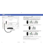
POWER AND STEERING WHEEL COMMANDS CONNECTIONS
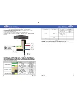
Power and steering wheel connections are located in the 22 poles connector as indicated.
Connect RED cable to the car radio 12VDC positive.
Connect BLACK cable to the ground.
Connect MAESTRO 2.0 BLUE-YELLOW cable to a positive ignition output.
The BLUE-YELLOW wire must not be connected if the vehicle uses CANBUS or GMLAN
protocol.
Connect steering wheel interface wires in series to the OEM wires, for example in a car
that uses CANBUS protocol is necessary to cut the CAN H wire and connect GREEN wire
to the car side and GREEN/YELLOW to the radio side, the same must be done with CAN L
and WHITE and WHITE/YELLOW wires.
GND
12 VDC
POSITIVE
IGNITION
JACK
AUX IN
CANBUS
R-LADDER
GMLAN
POWER
ANTENNA OUTPUT
FUNCTION
CANBUS WIRES
GREEN
CAN H INPUT
WHITE
CAN L INPUT
GREEN / YELLOW
CAN H OUTPUT
WHITE / YELLOW
CAN L OUTPUT
R-LADDER WIRES
PINK
V1 INPUT
YELLOW
V2 INPUT
PINK / BLACK
V1 OUTPUT
YELLOW / BLACK
V2 OUTPUT
GMLAN WIRES
GREY
GMLAN INPUT
GREY / YELLOW
GMLAN OUTPUT
WIRE COLOUR
MAESTRO 3.0 Blue
Rev 1.14
17
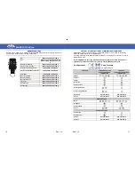
MAIN MENU
SUB-MENU 1
SUB-MENU 2
SUB-MENU 3
SETUP
SYSTEM
VERSION
BACK
EXIT
UPGRADE SYSTEM
INSERT KEY
BACK
EXIT
AUTO PWR (ON/OFF)
RDS TEXT (ON/OFF)
BACK
EXIT
BACK
EXIT
EXIT
MEANINGS
AUTO PWR
switches on automatically the interface when a new source is connected.
RDS MODE
changes the RDS version used: normal (8 characters) and estende (64 characters)


