


Set Up the Software
UI-5101
3
012-15849A
Mounting the Sensor
The Sound Sensor housing
includes a threaded hole
(1/4-20) on the bottom side.
Screw a Sensor Mounting Rod
into the threaded hole, and use
clamps and support rods to hold
the sensor in place.
Set Up the
Software
Software Help
See the PASCO Capstone Help for information about
collecting, displaying, and analyzing data.
•
In PASCO Capstone, select
PASCO Capstone Help
from the
Help
menu, or press
F1
.
PASCO Capstone
•
In the software, select
Hardware Setup
in the Tools
palette to open the Hardware Setup window. In the
Hardware Setup Window,
check that the Sound
Sensor icon is connected to the interface icon.
•
Select
Hardware Setup
again to close the window.
•
Select an Oscilloscope (Scope) display from
the
Display
palette.
•
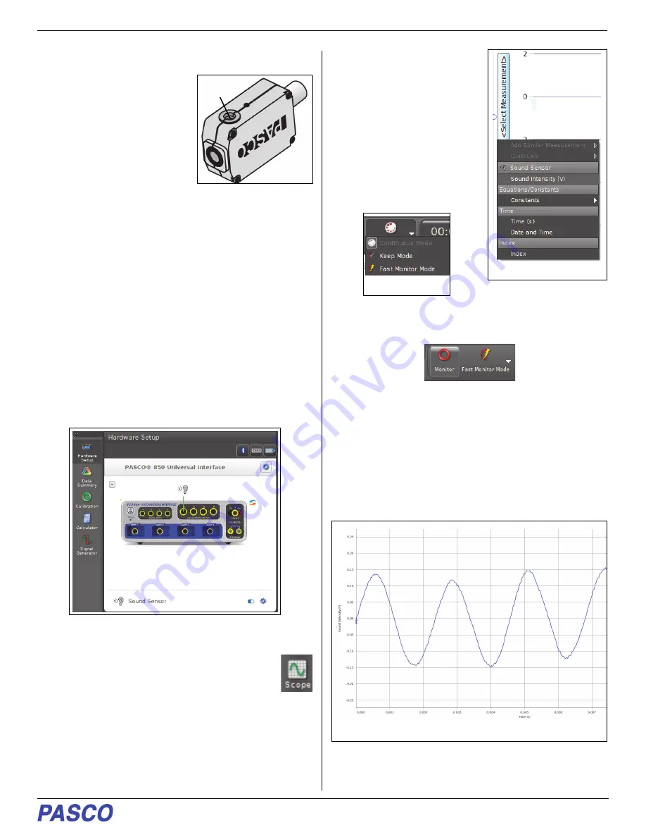
In the Scope display, use
the
<Select Measurement>
menu on the vertical axis to
pick a measurement to be
shown, such as Sound
Intensity (V).
•
In the
Controls
palette of
the Scope display, click
“Continuous Mode” to open
the menu. Select “Fast
Monitor Mode” from the
menu.
•
The “Record” button changes to “Monitor”,
•
In Fast Monitor Mode, the Scope display allows you to
view data much faster than you can in the Record
mode.
Collecting Data
•
Select
Monitor
to begin viewing data in the Scope
display.
Threaded
Hole
Select “Sound Intensity (V)”
Fast Monitor Mode
Example Scope display of sound data


