®
Gravitational Torsion Balance
Equipment Setup
6
012-11032C
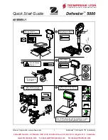
d.
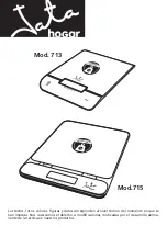
If the spots on the projection surface (the laser beam reflec-
tions) are not aligned vertically, loosen the zero adjust thumb-
screw, turn the zero adjust knob slightly to refine the
rotational alignment of the pendulum bob arms (Figure 10),
and wait until the movement of the pendulum stops or nearly
stops.
e.
Repeat steps 4a – 4c as necessary until the spots are aligned
vertically on the projection surface.
6.
When the rotational alignment is complete, carefully tighten
the zero adjust thumbscrew, being careful to avoid jarring the
system.
Hints for speedier rotational alignments:
•
Dampen any wild oscillations of the pendulum bob with the locking mechanisms, as described;
•
Adjust the rotational alignment of the pendulum bob using small, smooth adjustments of the zero adjust
knob;
•
Exercise patience and finesse in your movements.
Setting up for the Experiment
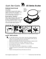
1.
Take an accurate measurement of the distance from the mirror to
the zero point on the scale on the projection surface (
L
) (Figure 8).
(The distance from the mirror surface to the outside of the glass
window is 11.4 mm.)
Note
:
Avoid jarring the apparatus during this setup procedure.
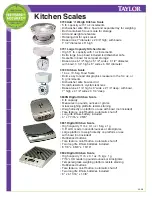
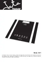
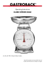
2.
Attach copper wire to the grounding screw (Figure 11), and ground
it to the earth.
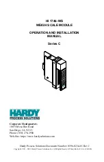
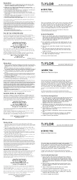
3.
Place the adapter rings on the support arm and place the large tung-
sten masses on the adapter rings, and rotate the arm to Position I
(Figure 12), taking care to avoid bumping the case with the masses.
4.
Allow the pendulum to come to resting equilibrium.
You are now ready to make a measurement using one of three meth-
ods: the final deflection method, the equilibrium method, or the
acceleration method.
Note
:
The pendulum may require several hours to reach resting
equilibrium. To shorten the time required, dampen the oscillation of
the pendulum by smoothly raising the locking mechanisms up (by
turning the locking screws) until they just touch the crossbar, hold-
ing for several seconds until the oscillations are dampened, and then
carefully lowering the locking mechanisms slightly.
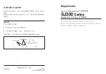
Zero adjust knob
Zero adjust thumbscrew
Figure 10: Refining the rotational
alignment of the pendulum bob
Attach to
Ear
th
Ground.
GR
AV
ITAT
IO
NA
L
TO
RS
IO
N B
AL
AN
CE
AP
-82
15
Grounding
screw
Copper wire to
earth ground
Light beam
Large Masses:
Position I
Large Masses:
Position II
Glass window
Mirror
Case
Figure 11: Attaching the ground strap
to the grounding screw
Small
mass