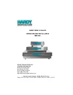
background image

HI 1746-WS

WEIGH SCALE MODULE

OPERATION AND INSTALLATION

MANUAL

Series C

Corporate Headquarters

10075 Mesa Rim Road

San Diego, CA 92121
Phone: (858) 278-2900
Web-Site: http

s

://www.hardysolutions.com

Hardy Process Solutions Document Number: 0596-0234-01 Rev 

J

Copyright  2011 

- 2023 

Hardy Process Solutions, Inc. All Rights Reserved. Printed in the U.S.A. (941028)

Summary of Contents for C Series

Page 1: ...Corporate Headquarters 10075 Mesa Rim Road San Diego CA 92121 Phone 858 278 2900 Web Site https www hardysolutions com Hardy Process Solutions Document Number 0596 0234 01 Rev J Copyright 2011 2023 Ha...

Page 2: ...audits and performance measurement Emergency troubleshooting and repair To request Emergency Service and Troubleshooting Start up Installation Calibration Verification or to discuss a Maintenance Agr...

Page 3: ...nt TTL Outputs 1 6 CHAPTER 2 SPECIFICATIONS 2 1 A Brief Description of Chapter 2 2 1 Specifications for a Standard HI 1746 WS Weigh Scale Module 2 1 Modes of Operation 2 1 Conversion Rate 2 1 Averages...

Page 4: ...3 1 Unpacking 3 1 Installing the HI 1746 WS into an Allen Bradley SLC 500 Processor or Allen Bradley Remote Rack 3 1 Setting the Jumper for Local or Remote Mode of Operation 3 2 Installing the HI 174...

Page 5: ...M0 file 4 8 For Example 4 8 Writing to the O file 4 8 For Example 4 8 Words 1 7 4 8 Reading from the 32 Word Logical I and logical M1 files 4 9 Command Word 4 9 Bits 15 14 set to 10 4 9 For Example 4...

Page 6: ...edures 4 28 Setting the Unit of Measure 4 28 Setting the Motion Tolerance Value 4 28 Setting the Zero Tolerance Value 4 29 Setting the Auto Zero Tolerance Value 4 29 Setting the Number of Readings Ave...

Page 7: ...ion Only 5 11 Hard Calibration 5 12 Hard Calibration Ladder Logic Example 5 12 CHAPTER 6 OPERATING PROCEDURES 6 1 A Brief Description of Chapter 6 6 1 Block Transfer Read 6 1 Block Transfer Read Examp...

Page 8: ...HI 1746 WS WEIGHT SCALE MODULE vi...

Page 9: ...5IT JUNCTION BOX WIRING DIAGRAM 3 9 CHAPTER 4 SETUP 4 1 FIG 4 1 MODULE LEDS 4 2 FIG 4 2 PRIMARY AND REMOTE COMMUNICATION DIAGRAM 4 7 FIG 4 3 SETUP I O FOR REMOTE MODE OF OPERATION 4 18 FIG 4 4 SETPARA...

Page 10: ...HI 1746 WS WEIGH SCALE MODULE II...

Page 11: ...practices either implied or expressed in this manual Before using the Weigh Scale Module all users and maintenance personnel should read and understand all cautions warnings and safety procedures refe...

Page 12: ...tains to the firmware software Setup and preparation procedures to calibrate and operate the instrument Chapter 6 Provides all Calibration instruc tions Chapter 7 Pertains to the Operating Proce dures...

Page 13: ...ications must be installed in a PC with either Ethernet DH DH 485 or RS 232 C that can initiate communications with the SLC 5 02 5 03 5 04 or 5 05 To calibrate the module you can simply push The Butto...

Page 14: ...s unique performance characteristics The HI 1746 WS reads the performance characteristics of each individual load sensor and detects the quantity of load sensors in the system C2 Calibration can be pe...

Page 15: ...e current voltage reading of an empty vessel The test displays a Passed Return to Zero Test or a Failed Return to Zero Test statement when running the System Test from the Configuration Software Test...

Page 16: ...pre set auto zero toler ance Note The amount of weight zeroed off is cumulative The zero command will fail if the current gross weight plus any previously zeroed amount exceeds the zero tolerance Set...

Page 17: ...e attempting an installation or repair of this instrument Specifications for a Standard HI 1746 WS Weigh Scale Module Modes of Operation Local and Remote Conversion Rate 20 updates per second Averages...

Page 18: ...t maximum of C2 authorized cable Maximum of 4 load sensors with IT Junction box Load Cell Excitation 5 VDC 1 15 W maximum Isolation from digital section 1000 VDC minimum C2 Calibration Output Isolatio...

Page 19: ...mmH x 158 75mmW x 114 3mmD Weight 5 pounds 2 27 Kilograms Enclosure Ratings SS Stainless Steel NEMA 4 4X PS Painted Carbon Steel NEMA 4 IT Junction Box HI 215IT FG Series Case Dimensions 6 50 H x 8 0...

Page 20: ...0 Auto Zero Tracking Enabled False 0 Tare Enabled True 1 Zero Enabled True 1 Calibration Type No Calibration 1 Setpoint Mode 1 2 Force Low Gross 0x12 Setpoint Value 1 2 10000 0 lbs Setpoint Deadband 1...

Page 21: ...dy Customer Support for assistance Unpacking Step 1 Before signing the packing slip inspect the packing for damage of any kind Step 2 Report any damage to the carrier company immediately Step 3 Check...

Page 22: ...e connector pins Never install remove or wire any module while the power is on Always disconnect the power from the SLC when working on the module Do not install the module right next to an AC or high...

Page 23: ...3 3 FIG 3 2 JUMPER LOCATION JUMPER SET IN THE DEFAULT OFF LOCAL MODE POSITION Installing the HI 1746 WS into the SLC 500 or Remote Chassis Step 1 Make sure that the module is oriented cor rectly for i...

Page 24: ...CB Guides on the top plate and bottom plate of the chassis to line up the module con nector with the backplane connector Step 4 When the module connector is touching the backplane connector firmly but...

Page 25: ...LEASE S FIG 3 5 MODULE INSTALLED IN SLC CHASSIS Removing the Module from the SLC 500 or Remote Chassis Step 1 Press down on the top and bottom Proces sor Releases simultaneously until the mod ule can...

Page 26: ...to the load sensors and relays or the HI 215IT Junction Box depending on how many load sensors are installed in the weighing system See below for the pin out diagram The pin out diagram is located on...

Page 27: ...I O connector at the front of the module Step 5 Check to be sure that the connector is completely plugged in before operating the module NOTE Most of the problems with modules are due to loose connec...

Page 28: ...e using C2 load cells remove the jumpers and connect the sense lines The jumpers or sense lines must be installed at all times WARNING Load cell cable length has been calcu lated into C2 calibration d...

Page 29: ...2 WIRING DIAGRAM Hardy HI 215IT Junction Box FIG 3 9 HARDY HI 215IT JUNCTION BOX WIRING DIAGRAM NOTE When connecting the Hardy HI 215IT Junction Box you must remove the two factory installed jumpers t...

Page 30: ...ppy drive Step 3 Click on START Step 4 Click on Run Step 5 In the Run field type the command a setup If your floppy drive is drive b enter b setup Step 6 Press the Enter key Step 7 You can also use th...

Page 31: ...the setup procedures The Setup procedures require either Allen Bradley DOS PLC 500 AI Series Ladder Logic Editor Allen Bradley RS Logix 500 Allen Bradley RSLinx or RSLinx Lite The Local Mode of Opera...

Page 32: ...teady Green Normal Operation Flashing Green Block transfer is being performed LED is Off No Communication C2 LED Steady Green A C2 load cell s has been found LED is Off No C2 load cells have been foun...

Page 33: ...a module output file a write only file and the M1 file is a module input file a read only file With respect to the HI 1746 WS weigh module the M1 file is for output from the module to the processor an...

Page 34: ...ows for all the parameters Parameter Word Tare Weight float 28 Span Weight float 30 CalLO Weight float 32 Set Point 1 float 34 Dead Band 1 float 36 Preact 1 float 38 Set Point 2 float 40 Dead Band 2 f...

Page 35: ...TION THIS SETUP INFORMATION IS FOR THE LOCAL MODE OF OPERATION ONLY BEFORE SETTING UP FOR LOCAL MODE OF OPERATION CHECK TO BE SURE THE JUMPER IS SET FOR LOCAL MODE AND THAT THE MODULE IS INSTALLED IN...

Page 36: ...he module s parameters the value of the parameter is written in the Datastring field Logical File Interface to Set Up for Remote Mode of Operation 8 Word CAUTION THIS SETUP INFORMATION IS FOR THE REMO...

Page 37: ...Word Bits 15 14 11 write 0 to 7 words to the logical M0 file Read 7 words from the M1 file NOTE You need to run any command through M files before previous writes take effect 01 write 0 to 7 words to...

Page 38: ...ds to the logical M0 file starting at offset word 28 Writing to the O file Bits 15 14 set to 01 will specify a write to the logical O file Bits 13 8 set as a binary value indicat ing number of words t...

Page 39: ...ight LSW net weight MSW net weight LSW relay status module status and ROC evaluation period Bits 15 14 set to 11 When written to the logical M0 file will cause the I file to reflect the words at the s...

Page 40: ...rent gross weight be set to zero Error Return Values NOTALLOWED the ZeroEnable parameter is not set to TRUE 1 OUTOFTOLERANCE the current weight value is beyond the limits set by the zero tolerance par...

Page 41: ...ding calibration constants to be saved to the non volatile memory Error Return Values None SEQ NUMBER 0 COMMAND Hex 1 STATUS 2 OFFSET 3 LENGTH 4 DATA 5 16 From M1 File 4 Reload Non Volatile RELOADNONV...

Page 42: ...2 OFFSET 3 LENGTH 4 DATA 5 16 From M1 File 0x96 Integer to Float Integer Conversion Command INT2FLOAT The Integer to Float Integer Conversion Command Converts a Float integer to an integer For use wi...

Page 43: ...Q NUMBER 0 COMMAND Hex 1 STATUS 2 OFFSET 3 LENGTH 4 DATA 5 16 From M1 File 0x64 Cal High Command CALHIGHCMD The Cal High Command Sets the Span Weight parameter to the current A D average counts when d...

Page 44: ...9 byte serial number from a C2 chip located on every C2 load cell Specify the index of the C2 chip to read in commandData offset of the Mfile The index should be a number of 0 to C2RomX 1 1 is a minus...

Page 45: ...lue from Table 4 1 See Weight Multi plier Sec tion Below Get Parameters Command GETPARAM Reads a parameter from the module See Setting the Process Weighing Parameters below for more detailed informati...

Page 46: ...HI 1746 WS WEIGH SCALE MODULE 4 16 I O Setup Ladder Logic for Remote Mode Operation...

Page 47: ...Chapter 4 Setup 4 17...

Page 48: ...guration Software Interface Remote Mode of Operation The HI WS100 program communicates with the remote HI 1746 WS module via an integer N7 N8 etc file as specified in the Comm Setup Section of the HI...

Page 49: ...logic program needs 17 contiguous words in the data file which are 1 N9 0 is the write trigger 2 N9 1 to N9 8 are write data loca tions 3 N9 9 to N9 17 are read data loca tions NOTE These can be from...

Page 50: ...ould be the same driver that RS Logix 500 would use 3 Station number of the processor is correct which can be found in the driver configuration 4 M file setup data i e N10 0 to N10 2 is correct for yo...

Page 51: ...be pounds or kilograms depending on the value of the Metric Parameter If the WEIGHTMULTIPLIER is zero the dataString value returned will be a floating point integer NOTE If using a multiplier setpoin...

Page 52: ...3 Reads the M1 file for the response Rung 4 Checks the results of the read to make sure that the sequence number was incremented write complete and that the status is zero no error If the check is go...

Page 53: ...Chapter 4 Setup 4 23 SETPARAMS Local Mode of Operation FIG 4 4 SETPARAMS LADDER LOGIC EXAMPLE LOCAL MODE...

Page 54: ...HI 1746 WS WEIGH SCALE MODULE 4 24 SETPARAMS Remote Mode of Operation...

Page 55: ...Chapter 4 Setup 4 25...

Page 56: ...HI 1746 WS WEIGH SCALE MODULE 4 26...

Page 57: ...loat 0x4C AutoZeroTolerance float 0x50 MotionTolerance float 0x54 Metric int 0 LBS 0x14 WAVERSAVER int limits 0 4 0x16 NumAverages int limits 1 255 0x24 ZeroTrackEnable int 0x26 TareEnable int 0x28 Ze...

Page 58: ...rams will take you to all the available Documents and Sample Programs for the HI 1746 The Unit of measure Metric See Table 4 1 can be set to either kilograms or pounds Any weight value input to the mo...

Page 59: ...eviously zeroed amount exceeds the zero tolerance Setting the Number of Readings Averages The Number of Averages sets the number of weight readings which will be used to compute the displayed weight T...

Page 60: ...HI 1746 WS WEIGH SCALE MODULE 4 30...

Page 61: ...rsonnel be familiar with the procedures contained in this chapter before installing or operating the HI 1746 WS Weigh Module Pre Calibration Procedures Step 1 Check to determine if the load cells have...

Page 62: ...objects c Check to see that nothing is coming in contact with the scale vessel other than service wires and piping that have been properly mounted with flexible connec tors FIG 5 1 PROPERLY INSTALLED...

Page 63: ...of the product as measured by the load cell point d If the load cell point weight capacity is rated at 1000 pounds the load cell point will be 10 mVDC at 1000 pounds 7 5 mVDC at 750 pounds 5 mVDC at...

Page 64: ...logic dis play reads 100 pounds and a 20 pound weight is placed on the vessel or scale the ladder logic display should read 120 or some value over 100 If the ladder logic display reads 100 pounds and...

Page 65: ...process See Chapter 4 Setup Step 2 Open the front door of the HI 1746 WS module See Fig 5 3 FIG 5 3 THE BUTTON C2 CALIBRATION NOTE If the module is being calibrated for the first time and your not su...

Page 66: ...See Chapter 4 Setup Step 2 We have provided a Ladder Logic for both the local and remote mode of opera tion example explaining how to perform the C2 Calibration Data Locations Used for Ladder Logic E...

Page 67: ...non volatile memory Rung 0 Does an initial read of the M1 file this is necessary to get the sequence number for future writes Rungs 1 5 Downloads a reference point value These rungs follow the same pa...

Page 68: ...HI 1746 WS WEIGH SCALE MODULE 5 8 C2 Calibration Ladder Logic Example For Local Mode of Operation Only...

Page 69: ...Chapter 5 Calibration 5 9...

Page 70: ...HI 1746 WS WEIGH SCALE MODULE 5 10 FIG 5 5 C2 LADDER LOGIC EXAMPLE LOCAL MODE OF OPERATION...

Page 71: ...Chapter 5 Calibration 5 11 C2 Calibration Ladder Logic Example For Remote Mode of Operation Only...

Page 72: ...ameters have been setup for your weighing process See Chapter 4 Setup Step 2 We have provided a Ladder Logic example explaining how to set the weigh process parameters The Ladder Logic example is mean...

Page 73: ...for the product you are calibrating e Click on the Ladder Logic Example for the HI 1746 WS Weigh Module Hard Calibration Step 4 For sample programs visit https www hardysolutions com hi1746 ws Use th...

Page 74: ...HI 1746 WS WEIGH SCALE MODULE 5 14...

Page 75: ...ale module or Write Data sent to the module It is very important that the user be familiar with this chapter before operating the weight scale module CAUTION THE OPERATING PARAMETERS ARE DIF FERENT FO...

Page 76: ...ror 7 No Excitation Error 8 15 Currently Not Used 7 Setpoint 2 Value 32 bit float or integer MSW 8 Setpoint 2 Value 32 bit float or integer LSW 9 Setpoint 2 Deadband 32 bit float or integer MSW 10 Set...

Page 77: ...t 1 loss in wght 4 Force low 5 Force high 6 Excitation Error 7 No Excitation Error 8 15 Currently Not Used 14 Weight Functions Bit Weight Functions 0 Zero 1 Tare 2 Write Non Volatile 3 Apply Settings...

Page 78: ...0 Communication Timeout Error 11 13 Currently Not Used 14 Command Error 14 15 Currently Not Used 16 Relay Status 17 Firmware Revision 18 Gross Weight 32 bit float or integer MSW 19 Gross Weight 32 bit...

Page 79: ...of the READWEIGHT Example Rung 0 Downloads the weight and rate multipliers one time Rung 1 Setpoint Status Weight and Rate of Change are copied from the input file for access 25 Increments on each wei...

Page 80: ...le FIG 6 1 READWEIGHT LADDER LOGIC EXAMPLE LOCAL MODE OF OPERATION Block Transfer Read Ladder Logic Example for Remote Mode Operation For Remote Mode Operation Block Transfer Read Examples go to the H...

Page 81: ...float or integer LSW 4 Setpoint 1 Preact 32 bit float or integer MSW 5 Setpoint 1 Preact 32 bit float or integer LSW 6 Setpoint 1 Mode Bit Setpoint Mode 0 ROC Rate of Change 1 Gross 2 Net 3 Gain Mode...

Page 82: ...t 2 Mode Bit Setpoint Mode 0 ROC Rate of Change 1 Gross 2 Net 3 Gain Mode 0 gain in wght 1 loss in wght 4 force low 5 force high 6 15 Currently Not Used 14 Weight Functions Bit Weight Functions 0 Zero...

Page 83: ...ing Procedures 6 9 Block Transfer Write Ladder Logic Example for Remote Mode Operation For Remote Mode Operation Block Transfer Write Examples go to the Hardy Website http www har dysolutions com and...

Page 84: ...HI 1746 WS WEIGH SCALE MODULE 6 10...

Page 85: ...on of Chapter 6 6 1 About C2 Calibration 5 4 About Hardy Manuals 1 2 About Logical Files 4 6 About M Files 4 3 About the Ladder Logic Example 4 20 About the Module I O Connector 3 6 Add Remove Functio...

Page 86: ...ALCMD 4 13 C2 Calibration 5 4 C2 Calibration Input 2 2 C2 Calibration Ladder Logic Example For Local Mode of Operation Only 5 8 C2 Calibration Ladder Logic Example For Remote Mode of Operation Only 5...

Page 87: ...ogic Level Outputs 1 6 Digital Volt Meter DVM 1 5 Digital Voltmeter 2 3 Direct M File Mapping 4 3 DVM Readings 1 5 E Electrical Check Procedures 5 2 Enclosure Rating 2 3 Enclosure Ratings 2 3 Environm...

Page 88: ...WS100 Configuration Software Interface Remote Mode of Opera tion 4 18 Humidity Range 2 2 I I O Setup Ladder Logic for Remote Mode Operation 4 16 Industry Standard Load Cells 3 8 Input 2 1 Installing...

Page 89: ...5 1 M File Interface to Set Up for Local Mode of Operation 4 5 M files 4 5 M0 File 4 3 4 5 M1 File 4 3 4 5 Mapping 4 4 Maximum Zero Tolerance 2 1 Modes of Operation 2 1 Module Connector 3 4 Module Doo...

Page 90: ...rs Command SETPARAM 4 14 Set Point 1 2 Out 2 2 Set Point TTL Outputs 1 6 SETPARAM GETPARAM Command and Non Volatile Memory 4 21 SETPARAMS Local Mode of Operation 4 23 SETPARAMS Remote Mode of Operatio...

Page 91: ...WAVERSAVER 2 1 WAVERSAVER 1 1 Weighing System Tests 1 5 Weight 2 3 Weight Multiplier 4 20 Windows NT 95 98 3 10 Windows 95 98 NT 1 3 Words 1 7 4 8 Write Data 6 1 Write Non Volatile Command WRITENONVOL...

Page 92: ...HI 1756 WS MANUAL...

Reviews: