!"#6!%&!#'
()*+,-*-,./*012.)3,./1'*0*/45
17
M
a
i
n
t
e
n
a
n
ce
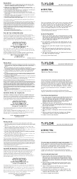
Replacing the Torsion Ribbon Assembly
If the torsion ribbon breaks, replace it as follows:
1.
Remove the plates, and raise the locking mechanism using
the locking screws until the pendulum arms are securely
anchored (Figure 21a).
2.
Grasp the pendulum bob near the bottom ribbon tab to
stabilize it.
3.
Loosen the Phillips screw on the bottom tab of the torsion
ribbon assembly (Figure 21a), and remove the bottom half
of the broken ribbon assembly.
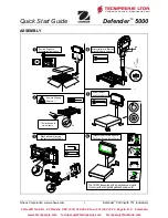
4.
Loosen the Phillips screw at the top of the balance
assembly (Figure 21b).
5.
Grasp the torsion ribbon head and remove the top portion
of the broken torsion ribbon assembly.
6.
Attach the top tab of the new torsion ribbon to the torsion
ribbon head using the Phillips screw, being sure the
copper disc on the tab is in contact with the torsion ribbon
head (Figure 22). Align the tab with the face of the torsion
ribbon head.
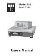
➀
Turn locking screws until
locking mechanism anchors
the pendulum arms.
➂
Loosen
the Phillips
screw.
locking
mechanism
broken
torsion
ribbon
➁
Grasp the
pendulum bob here
to stabilize it.
➃
Loosen the
Phillips screw.
Figure 21
Securing the pendulum bob before
removing a broken torsion ribbon, and
loosening the torsion ribbon head
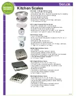
➄
Grasp the torsion
ribbon head and remove
the top portion of the
broken ribbon assembly.
The copper
disk must
contact the
torsion
ribbon
head.
Attach the tab with
the Phillips screw.
torsion
ribbon
ribbon tab
torsion ribbon head
Figure 22
Attaching the top tab of the torsion ribbon assembly to the torsion
ribbon head
"
!
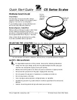
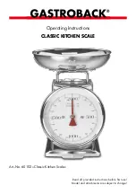
7.
Thread the ribbon through the shaft.
8.
Using the zero adjust knob, align the bottom tab with the
face of the pendulum bob.
zero adjust
knob
Summary of Contents for AP-8215
Page 24: ......