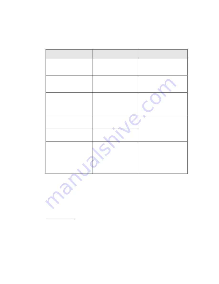
Partner LM12 Series User Manual Download Page 14


14 


Troubleshooting 


Many problems can be the result of an incorrect or loose cable connection, so please make 
sure that all connections are secure. 


Fault 

Possible cause 

Remedy 

LED on front panel lights up, 
but LCD monitor remains 
dark. 

Computer is switched off. 

Turn computer power ON. 

LED on front panel lights up, 
and LCD monitor lights up 
red and no picture appears. 

VGA cable is not correctly 
connected. 

Check cable connection of 
VGA connection including pins 
on connector. 

The display shows only part 
of the picture or the picture is 
distorted. 

Display resolution is set to 
an incompatible setting. 

Resolution should be set to 
800x600 or less. 

LCD shows indistinct vertical 
stripes. 

Display 

H.POSITION

 is not 

set correctly. 

LCD shows fine horizontal 
stripes. 

PHASE

 adjustment is not 

correctly set. 

Use the 

AUTO TUNE

 feature. 

(see 5.2.7)


Touch does not work under 
DOS or Windows 3.1 
 
Touch cannot be calibrated 
under Windows because the 

calibrate

 button is not active. 

RS-232 cable connection 
may be incorrect. 

Check serial cable connection 
and restart computer. While 
booting, check for any 
indication of driver errors. 
Check touchscreen with 
diagnostic program 

COMDUMP

 (see Elo utilities) 


8.1  Additional help 


If you have problems with the connection or the installation of the 

LM12 series

 monitor, please 

contact your distributor or direct to the manufacturer: 
 

Partner Tech Corp. 

Tel:  (8862) 2918-8500 
Fax: (8862) 2915-3405 

www.partner.com.tw

 or [email protected] 

 
When returning the device, the original packing 

must

 be used; otherwise the sender will be 

responsible for any transport damage. 
 

Summary of Contents for LM12 Series

Page 1: ...LM12 Series LCD Monitor User Manual ...

Page 2: ...____________________________________________________________________ 9 5 2 4 PHASE____________________________________________________________________ 9 5 2 5 RECALL___________________________________________________________________ 9 5 2 6 RETURN___________________________________________________________________ 9 5 2 7 AUTO TUNING____________________________________________________________ 10 5 ...

Page 3: ..._________________________________ 15 9 6 Environmental conditions ________________________________________________________ 15 9 7 ESD and EMV behavior__________________________________________________________ 16 9 8 Resistance to jamming ___________________________________________________________ 16 10 Safety Instructions _____________________________________________________ 17 11 Further Notices_...

Page 4: ...4 1 LM12 Series Model Number Definition LM12 X X X X T Touchscreen M Magnetic Card Reader S Single Back Light D Double Back Light B Charcoal Housing ...

Page 5: ... environmental conditions such as liquid spills and splashes humidity these screens are the most contamination resistant available They deliver drift free operation for a lifetime of 35 million finger touches AccuTouch technology is the workhorse of resistive touchscreens providing unsurpassed performance in POS industrial medical and transportation applications Touch the screen with a finger glov...

Page 6: ...just the display for the graphic card in the computer by means of the On Screen Display OSD AUTO TUNING feature This step is important for getting the best picture quality section 5 2 5 Touchscreen Monitor Only Install the touchscreen drivers for the corresponding operating system chapter 4 Note The LM12 must be used with the power adapter provided 4 1 Cable Installation The installation of the ca...

Page 7: ...on you will then see the Basic Settings menu appear figure 2 Figure 1 Button Descriptions for the On Screen Display The various menus and sub menu options are selected by using the UP and DOWN arrow buttons After making a selection use the buttons to activate that setting Once all adjustments have been made you can exit the OSD by selecting EXIT and pressing one of the buttons Figure 2 On Screen D...

Page 8: ...ortable setting 5 1 2 CONTRAST This selection adjusts the screen contrast Use the buttons to increase or decrease the contrast to a comfortable setting 5 1 3 DISPLAY ADJUST See section 5 2 5 1 4 COLOR CONTROL See section 5 3 5 1 5 OTHERS See section 5 4 5 1 6 INFORMATION This selection displays the current resolution horizontal and vertical refresh rates 5 1 7 RESET This selection displays restore...

Page 9: ... the buttons 5 2 2 V POSTION This selection adjusts the Vertical screen position using the buttons 5 2 3 CLOCK This selection adjusts the Clock speed using the buttons 5 2 4 PHASE This selection adjusts the Phase using the buttons 5 2 5 RECALL This selection will recall any previously stored settings before any changes were made 5 2 6 RETURN This selection returns to the Basic Settings menu ...

Page 10: ... variety of industry standard video cards To get the best picture quality under Windows it would be best to use the Shutdown screen when activating the AUTO TUNING menu option By doing this the display tries to find the best possible adjustment Please note that this AUTO TUNING must be done for each display mode The PHASE option may also be used to manually fine tune the picture clarity after AUTO...

Page 11: ... MODE This selection allows each of the main color parts of the picture can be adjusted individually By doing this the color tone can be adjusted to a comfortable level 5 3 2 RECALL This selection will recall any previously stored settings before any changes were made 5 3 3 RETURN This selection returns to the Basic Settings menu ...

Page 12: ...adjusts the amount of time the On Screen Display OSD will be displayed on the screen This can be adjusted by using the buttons 5 4 4 POWER SAVE This option enables disables the power saving mode feature 5 4 5 DITHERING This option enables disables the dithering feature Dithering is the simulation of more colors and shades in a palette by creating a pattern of dots out of existing colors 5 4 6 RECA...

Page 13: ...ated in the file D TOUCH ELO README TXT 6 2 Magnetic Card Reader Setup The setup utility can be found on the installation CD at D MSR SETUP EXE Drive D shown above may vary on each system 6 3 Diagnostics Utility The diagnostic program COMDUMP is located in the path D TOUCH and must be used in DOS or command prompt mode Usage COMDUMP number of COM port 1 or 2 baud rate Baud rate is optional COMDUMP...

Page 14: ...y H POSITION is not set correctly LCD shows fine horizontal stripes PHASE adjustment is not correctly set Use the AUTO TUNE feature see 5 2 7 Touch does not work under DOS or Windows 3 1 Touch cannot be calibrated under Windows because the calibrate button is not active RS 232 cable connection may be incorrect Check serial cable connection and restart computer While booting check for any indicatio...

Page 15: ...tness 300 cd m2 100cd m2 typical Contrast 150 1 typical Resolution SVGA 800x600 maximum Colors 262 144 6 Bit RGB Refresh rate vertical 70 HZ 640x350 DOS text mode 60 Hz 72 Hz 75 Hz 640x480 60 Hz 800x600 Durability of backlight 30 000 hours typical 9 4 Touch Interface RS 232 Technology 5 wire resistive Resolution 800x600 Surface Hard coated polyester foil Transmission 75 EloTouch Controller E271 22...

Page 16: ...ss Modulation 3 V m 3 Fast transient burst immunity electrical interference features according to EN 61000 4 4 Criteria B hardness 1 KV for AC power 4 Surge immunity test according to EN 61000 4 5 Criteria B 5 Immunity for conductive disturbance test according to EN61000 4 6 Criteria B level is 3V Modulation 6 Power frequency magnetic field test EN 61000 4 8 Criteria B 1A m 7 Voltage dips short in...

Page 17: ... can cause disturbances and damage in usage In case you modify the product in any way we do not assume warranty and liability unless you have an explicit release in writing for your specific case This applies especially to unprofessional repair and maintenance jobs Any claims for damages against the manufacturer of the LM12 no matter for which legal reasons are excluded if no intention and gross n...

Page 18: ...icular installation If this equipment does cause harmful interference to radio or television reception which can be determined by turning the equipment on and off the user is encouraged to try to correct the interference by one of the following measures Reorient or relocate the receiving antenna Increase the separation between the equipment and receiver Connect the equipment into an outlet on a ci...

Reviews: