


CD7220/CD3220 CUSTOMER DISPLAY
10
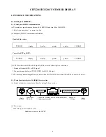
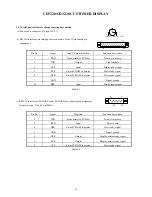
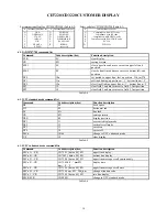
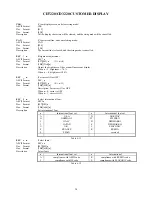
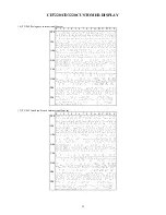
4.1.3 Serial port interface to the space-saving base portion
(a) Power cable connector: DC jack (5.5/2.1)
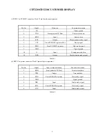
(b) RS232C interface pass through cable connector: D-sub 25 pin female pin
assignment
Pin No.
Signal
Input / Output direction
Function description
2
RXD
From printer to PC/Host
Printer status data
3
TXD
Output
Transmit data
4
CTS
Input
Printer ready signal
5
RTS
From PC/HOST to printer
Host ready signal
6
DTR
From PC/HOST to printer
Host ready signal
7
GND
Signal ground
20
DSR
Input
Printer ready signal
Table 4-3
(c) RS232C interface to PC/HOST cable, PC/HOST side connector pin assignment
Connector type: D-sub 9 pin (Male)
Pin No.
Signal
Direction
Function description
2
TXD
From printer to PC/Host
Printer status data
3
RXD
Input
Receive data
4
DSR
From PC/HOST to printer
Host ready signal
5
GND
Signal ground
6
DTR
Output
Display/printer ready signal
7
RTS
Output
Display/printer ready signal
8
CTS
From PC/HOST to printer
Host ready signal
Table 4-4
GND 5V or 12V
1
13
14
25
1
9
6
5


