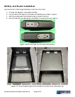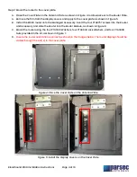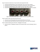
Step 4: Connect the router to the RJ-45 ports on the case using ethernet cords.
A.
Connect the provided ethernet cords to the LAN ports on the router, shown in Figure 8.
B.
Connect the other ends of the ethernet cords from the router to the RJ-45 ports on the case.
C.
Connect the provided ethernet cord to the WAN port on the router, shown in Figure 8.
D.
Connect the other end of the ethernet cord from the router to the RJ-45 port on the cover plate.
Figure 12: Connect the router to the RJ-45 ports on the case using ethernet cords.
Step 5: Connect the USB-A port on the case to the router.
A.
Connect one end of the provided USB-A cord into the USB-A port on the case.
B.
Connect the other end of the USB-A cord into the USB-A port on the router, shown in Figure 8.
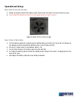
Step 6: Connect the battery pack to the USB-C charging port on the case.
A.
Connect the USB-C charging port cable from the case to the USB-C port on the battery, shown in
Figure 11.
LAN 1
LAN 3
LAN 4
LAN 2


