background image

Installation and Startup

2-14

CameraMan

 1-CCD Camera System Installation and Operations Manual

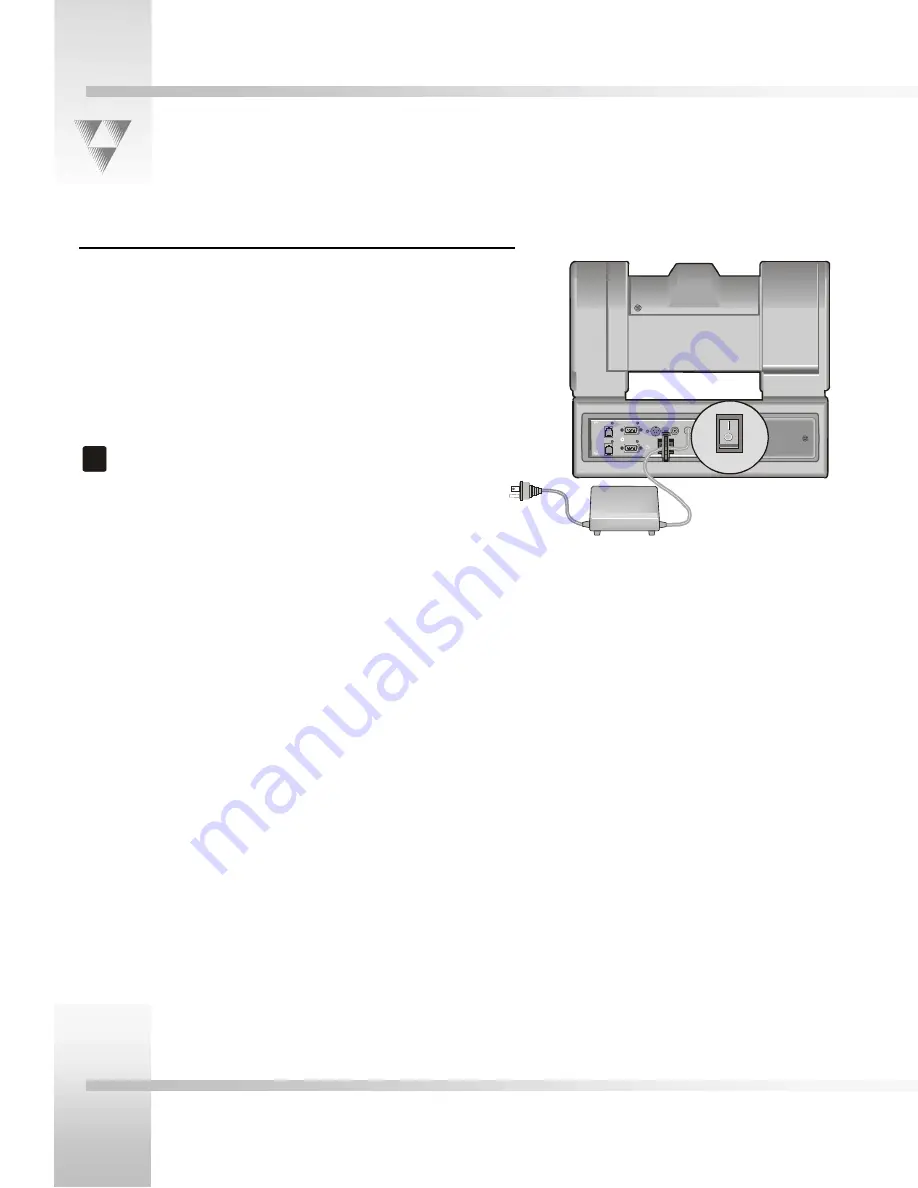
Connecting the Power Supply

You can mount the power supply with any orientation or on top of a
table or roll-about unit. Follow the steps below:

1.

Verify that the power switch located on the back of the camera
is turned off.

2.

Plug the 5.5mm female connector of the power supply into the
DC POWER jack on the back of the camera.

3.

Connect the other end of the power supply into a 120 VAC
source.

!

Do not modify the length of the AC or the DC wiring.

PVI COM

RS-232

AUX A

S-VI DEO 

OUT

COM POSITE 

VIDEO OUT

DC 

POWER 

RS-485

POWER

POWER

Summary of Contents for CameraMan 1-CCD

Page 1: ...CameraMan 1 CCD General Pan Tilt Camera System Installation and Operations Manual ...

Page 2: ... FL 32256 800 532 8034 customer support 904 737 1367 phone 904 731 0958 fax support parkervision com e mail http www parkervision com web site CameraMan 1 CCD General Pan Tilt Camera System Installation and Operations Manual 2000 ParkerVision Inc ...

Page 3: ...ly 1 5 Connection Accessories 1 5 CAMERAMAN JACKS AND SWITCHES 1 6 Connection Jacks 1 6 INSTALLATION AND STARTUP 2 1 MOUNTING YOUR CAMERAMAN CAMERA 2 1 CONNECTING TO THE CAMERA SYSTEM 2 2 Restraining the Cable Connections 2 2 Connecting the Video Output 2 2 Connecting to the RS 232 Port 2 3 Connecting the Power Supply 2 4 CONNECTING CAMERA CONTROL DEVICES 2 5 Camera Control Keypad or Tracking Syst...

Page 4: ......

Page 5: ...lerts you to tips or noteworthy suggestions in the operation use or maintenance of your CameraMan system Support Information The manufacturer reserves the right to change specifications and warranty at any time without notice or obligation Refer all warranty and servicing issues to ParkerVision Customer Support at 1 800 532 8034 Section 1 Copyright Information The following terms are registered tr...

Page 6: ...mponents One 1 CCD CameraMan camera One CameraMan connector box not included in Presenter Systems One CameraMan power supply One RS 485 T connector One 3 CameraMan communications cable One 25 CameraMan keypad cable One 1 CCD Installation and Operations Manual Product Description You can control 1 CCD CameraMan s pan tilt functions zoom perspective and IMAGE settings using ParkerVision s Camera Con...

Page 7: ...era automatically follows their every move Includes Tracking Ring Package Tracking System Keypad and Main Docking Station Personal Locator Camera Upgrade Package Best for Videoconferencing applications This system gives each videoconferencing participant the power to be instantly identified by the camera with the touch of a MY TURNTM button on individually controlled wireless keypads Includes Thre...

Page 8: ...tiple camera application You simply install it into the interface on the rear of the camera The bright red indicator mounts to the top of a flexible shaft allowing precise adjustment and positioning of the light for the best possible studio wide observation You can control the Tally Light through ParkerVision s CONTROL Center STUDIO software or through an external contact closure connected to a si...

Page 9: ...point for all RS 232 RS 485 power and video signals The only time you would need to remove this box is when you are connecting this camera to a Main Docking Station included with the Presenter and Deluxe Camera Systems If you purchased a Presenter or Deluxe Camera System you do not need a connector box CameraMan Power Supply The power supply enables use with 120 VAC sources International Models in...

Page 10: ...h as PCs or other vendor control systems S VIDEO Jack A standard min DIN jack that provides direct S VIDEO video output S VIDEO cable is not provided Cable Restrainer Helps keep cables from becoming dislodged or hindering the pan and tilt of the camera Composite Video Jack A standard BNC type jack that provides direct composite video output Video cable is not provided DC Power Jack Power input for...

Page 11: ...icator mark in the direction that best reflects the center of travel for the camera This is usually the center of the room Lift the unit by its base not by its tilt assembly 3 To ensure that the mounting surface is not prone to vibrations fasten the camera to a flat rigid surface using a 1 4 20 UNC cap screw that does not extend into the base platform by more than 0 4 The cap screw is not included...

Page 12: ...e restrainer on the back of the camera Connecting the Video Output CameraMan supports both composite and S VIDEO formats although you can use only one at a time For composite format connect to the BNC jack on the Connector Box on the back of the camera labeled COMPOSITE VIDEO OUT using a standard coaxial cable with a BNC connector not provided Verify that the Video Select switch is set to COMPOSIT...

Page 13: ...can use this port to control the camera using external devices such as a PC or other vendor control system such as AMXTM and CrestonTM Our RS 232 protocol is available by calling Customer Support at 800 532 8034 Connect to this port using a standard computer cable with a DB 9 connector This port operates with No Parity and software hand shaking using ParkerVision High Reliability or Basic protocol...

Page 14: ... unit Follow the steps below 1 Verify that the power switch located on the back of the camera is turned off 2 Plug the 5 5mm female connector of the power supply into the DC POWER jack on the back of the camera 3 Connect the other end of the power supply into a 120 VAC source Do not modify the length of the AC or the DC wiring PVI COM RS 232 AUX A S VI DEO OUT COM POSITE VIDEO OUT DC POWER RS 485 ...

Page 15: ... beeps indicating that the keypad is ready for operation The light located above the PVI COM port indicates communication activity Use only the cable supplied by ParkerVision for the PVI COM port Using non ParkerVision cables such as telephone cords may cause damage SHOT Director You can connect the optional SHOT Director joystick controller in hard wired mode only To connect the SHOT Director to ...

Page 16: ...ng the two screws holding it in place Behind the plate you will see all of the configuration switches Refer to the next page for a table describing the switches UP DOWN SWITCH BANK A SWITCH BANK B 1 2 3 4 5 6 7 8 1 2 3 4 5 6 7 8 S VIDEO COMPOSITE BASE UNIT ADDRESS Up Down This diagram shows the default switch configuration of the camera as shipped UP DOWN SWITCH BANK A SWITCH BANK B 1 2 3 4 5 6 7 ...

Page 17: ...era If you use the optional keypad SHOT Director or another control system refer to the documentation provided with those accessories for proper configuration For setting up a camera network refer to Appendix A Multiple Camera Applications B1 Protocol High Reliability Basic DOWN Use this switch to select the communication protocol to be used by the RS 232 and RS 485 ports The High Reliability prot...

Page 18: ...FRONT label was pointing during mounting Refer to the Mounting Your CameraMan Camera topic in this section 3 If you are using the optional Camera Control Keypad make sure its address is the same as the address on the camera Also verify that the camera s pan and tilt functions are working properly If the camera does not move refer to the Troubleshooting section of your Camera Control Keypad or SHOT...

Page 19: ......

Page 20: ...s 0 camera 2 set with address 1 etc 4 In order to control each camera with your Camera Control Keypad the rotary switch inside the keypad battery compartment must match the lowest base unit address in your system Only one base unit should have its RF enabled Refer to the Switch Configuration topic of Section 2 Installation and Statup EXAMPLE If the BASE UNIT ADDRESS switches are set according to t...

Page 21: ...l Automatic or Manual Image Control Automatic or Manual Mechanical Devices WhisperDRIVE PlusTM rated for 5000 hrs of continuous motion Tilt 25 speed 1 sec to 50 sec Pan 359 speed 1 sec to 65 sec Location Presets 125 via software or CCK Location Preset Accuracy 125 Temperature 32 to 100 F 0 to 37 78 C Video Out 75 ohm Composite or S VIDEO NTSC VBS 1 0 Vp p Composite Y 1 0 Vp p Sync Negative C Burst...

Page 22: ... Below is a typical setup for your CameraMan camera The items in the diagram are not to scale Power Supply 2 3 1 LocationP resets C am eraM an auto IMA GE 1 3 5 7 9 2 4 6 8 0 IN E NTE R P A R K E R V I S I O N PVI COM RS 485 RS 232 Composite Video Out S Video Out Camera Control Video Output AMX OR Creston ...

Page 23: ... RS 485 Four position Module Handset 6 1 PVI COM RJ 11 Y C Y Ground C Ground S VIDEO Connector Video 1Vpp Ground Composite Video BNC Connector 18v DC Ground 5 5mm DC Power Connector 1 6 5 9 9 pin Female DB 9 Sub Pin Signal___ 1 Ground 2 Signal A 3 Signal B 4 Ground Pin Signal___ 1 12v 2 12v 3 Ground 4 Signal A 5 Signal B 6 Ground Pin Signal____ 2 Transmit 3 Receive 5 Ground 1 4 6 9 Not used ...

Page 24: ...0 63 51 47 66 5 26 4 03 Angle of View 48 8 37 6 4 3 3 3 Wide Angle Lens Adapter 0 65x f l 3 4 to 42 1 mm Distance from Lens No Zoom Full Zoom feet Horizontal ft Vertical ft Horizontal ft Vertical ft 10 14 28 10 33 1 16 0 88 15 21 42 15 49 1 74 1 32 20 28 56 20 65 2 32 1 76 25 35 70 25 82 2 90 2 20 30 42 84 30 98 3 48 2 64 35 49 98 36 15 4 05 3 07 40 57 12 41 31 4 63 3 51 45 64 26 46 47 5 21 3 95 5...

Page 25: ...s connected to the appropriate video input on the switcher CODEC or monitor 4 Verify that the video cables are good Try a different one if possible 5 Verify that the monitor s is working Problem There are no communications through the RS 232 port Solution 1 Verify that the cable is wired correctly 2 Verify that Switch Bank B Switch 1 PROTOCOL SELECT on the back of the camera is set properly 3 Veri...

Page 26: ...sly noted Proof of Purchase ParkerVision s authorized Dealer s dated bill of sale must be retained as evidence of the date of purchase and to establish warranty eligibility ParkerVision will correct all defects in material or workmanship or any failure of the system to perform to specifications during the warranty period at no charge for parts and labor The original purchaser must notify ParkerVis...

Page 27: ...Appendices CameraMan 1 CCD Camera System Installation and Operations Manual 3 9 ...

Page 28: ...t equipment 1 2 CODEC 3 6 COM light 3 6 components camera 1 5 composite video jack 1 6 2 2 composite video out 3 6 configuration multiple camera applications 3 1 configuration switch 2 5 connecting power to the camera 2 3 connecting to the camera system 2 2 connection accessories 1 5 connection ports 2 2 connections auxiliary communication port 1 6 composite video jack 1 6 DC power jack 1 6 gen lo...

Page 29: ...cator light 1 4 information about this manual 1 1 customer support 1 1 general 1 1 product 1 2 upgrade packages 1 3 installation and setup 2 1 instructions for connecting to the camera system 2 2 introduction to CameraMan 1 1 J jacks auxiliary communication port 1 6 composite video 1 6 DC power 1 6 gen lock 1 6 PVI COM 1 6 RS 232 port 1 6 RS 485 1 6 S VIDEO 1 6 tally light port 1 6 jacks and switc...

Page 30: ... 2 RS 232 port 1 6 2 3 3 2 RS 485 jack 1 6 RS 485 port 3 2 S S N ratio 3 2 SCRIPT Viewer display 1 4 setting up gen lock 2 7 setting up your camera 2 1 setup and installation 2 1 shortest subject distance 3 2 SHOT Director 1 4 SHOT Director joystick controller connection 2 4 shutter 3 2 specifications camera 3 2 field of view 3 5 starting up the system 2 7 student camera package upgrade 1 3 STUDIO...

Page 31: ...Installation and Operations Manual 4 13 V VAC source 2 3 VAC sources 1 5 vertical resolution 3 2 video out 3 2 video output connections 2 2 videoconferencing 1 3 W warranty information 3 7 white balance 3 2 wide angle lens 3 5 Z zoom 3 5 ...

Page 32: ... 2000 ParkerVision Inc Literature Part Number L1204101 REF LPMCPT1B Revision D ...

Reviews: