Installation and Startup
CameraMan
1-CCD Camera System Installation and Operations Manual
2-13
!
Verify that the Video Select switch is set to
S-VIDEO.
The switch is located behind the switch plate on
the
back right of the camera.
Refer to the "Switch
Configuration" topic in this section.
For video output specifications, refer to Appendix B,
Camera Specifications.
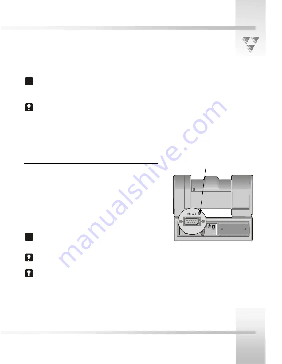
Connecting to the RS-232 Port
CameraMan
provides for RS-232 communications using the DB-9
jack on the back of the camera, labeled RS-232. You can use this
port to control the camera using external devices such as a PC or
other vendor-control system such as AMX
TM
and Creston
TM
.
Our RS-232 protocol is available by calling Customer Support at
(800)532-8034.
Connect to this port using a standard computer cable with a DB-9
connector. This port operates with No Parity and software hand-
shaking using ParkerVision High Reliability or Basic protocols.
!
Verify the protocol being used by checking the Protocol
switch on the camera. Refer to the "Switch
Configuration" topic in this section.
The COM light above the
RS-232
port is used to indicate
communication activity.
For the DB-9 pin-out port information, refer to Appendix
D, Pin-out Diagrams.
COM light
Summary of Contents for CameraMan 1-CCD
Page 1: ...CameraMan 1 CCD General Pan Tilt Camera System Installation and Operations Manual ...
Page 4: ......
Page 19: ......
Page 27: ...Appendices CameraMan 1 CCD Camera System Installation and Operations Manual 3 9 ...
Page 32: ... 2000 ParkerVision Inc Literature Part Number L1204101 REF LPMCPT1B Revision D ...


