Parker WCS-SIF-01 Training & Maintenance Manual Download Page 4

4

WCS-SIF-01

Training & Maintenance Manual

Pneumatic

Parker Hannifin Corporation

Pneumatic Division

Richland, Michigan

www.parker.com/pneumatics

Installation & Setup Instructions

Installation – Air and Electrical

A. Installing Weld Block with Existing Equipment

  1. Shut off air supply to weld gun and turn power off to cell.
  . Disconnect air hoses from existing weld block ports.  This 

will vary depending on weld gun type, and whether the 
existing weld block is single or dual pressure.

   Note: If the current weld block is mounted directly to the 

cylinder, then only the inlet port hoses will be disconnected.

  3. Disconnect solenoid connectors from valves.  Be sure 

to note which connectors are being used for pre-stroke 
(retract) valves and weld stroke valves.

  4. Remove current weld block from gun.

B. Installing Weld Block on New Equipment

  5. Mount weld block spotwelding system to robot using (4) M8 

screws and torque to 130 to 145 in. lbs (14.7 to 16.4 Nm).

  6. Connect all air hoses to weld block (see schematic on 

pages  or 3).

   Note: An additional air hose may be necessary for the 

inlet, since this unit is dual pressure.  If so, connect the 
already existing hose to the Pw port (pressure weld).  
This hose should be supplying scheduled pressures from 
a proportional regulator.  Connect the additional hose 
before the proportional regulator using a T-fitting so that 
full line pressure is being used.  This hose should be 
connected to the Pr port (pressure retract).

  7. Connect the solenoid cables to the proper valves.  

Connect an M1 sensor cable to the feedback sensor on 
the unit.  The other end of this cable should be wired to 
the PLC controller.

  8. Turn air supply and power on.
  9. Check for air leaks.  The weld cylinder should be in the 

home position (completely open).  If not, check that all 
air hoses are connected to the correct ports.  Verify that 
all solenoids are de-energized, and valve overrides are 
unactuated.  Once this is done, verify the function of the 
weld block, by actuating the weld block valves using the 
manual overrides.  Press and hold the retract (pre-stroke) 
valve manual override.  The weld cylinder should move to 
the weld stroke position.  Press and hold the weld stroke 
valve manual override [still holding the retract (pre-stroke) 
override].  The weld cylinder should now close.  Release 
the weld stroke override and the retract (pre-stroke) 
override.  The weld cylinder will return to home position.


Note:

 The weld stroke portion of the cylinder will move 

slower than the pre-stroke.  This is due to the regulated 
pressure being used, as well as the flow control.  
Adjusting the speed of the cylinder will be covered in the 
Setup Instructions.  Repeat this process, now energizing 
the solenoids.  The cylinder should perform the same.  If 
not, verify that the solenoid connectors are located on the 
proper valves.  Once the unit has been properly installed, 
the following setup procedure can be used to ensure that 
the Parker weld system is used to its fullest potential.

Wiring


Refer to valve Instruction Sheet for proper wiring connections.  
Available at: www.parker.com/pneumatic (see B6 and ISO 
size  valves Installation and Service Instructions).

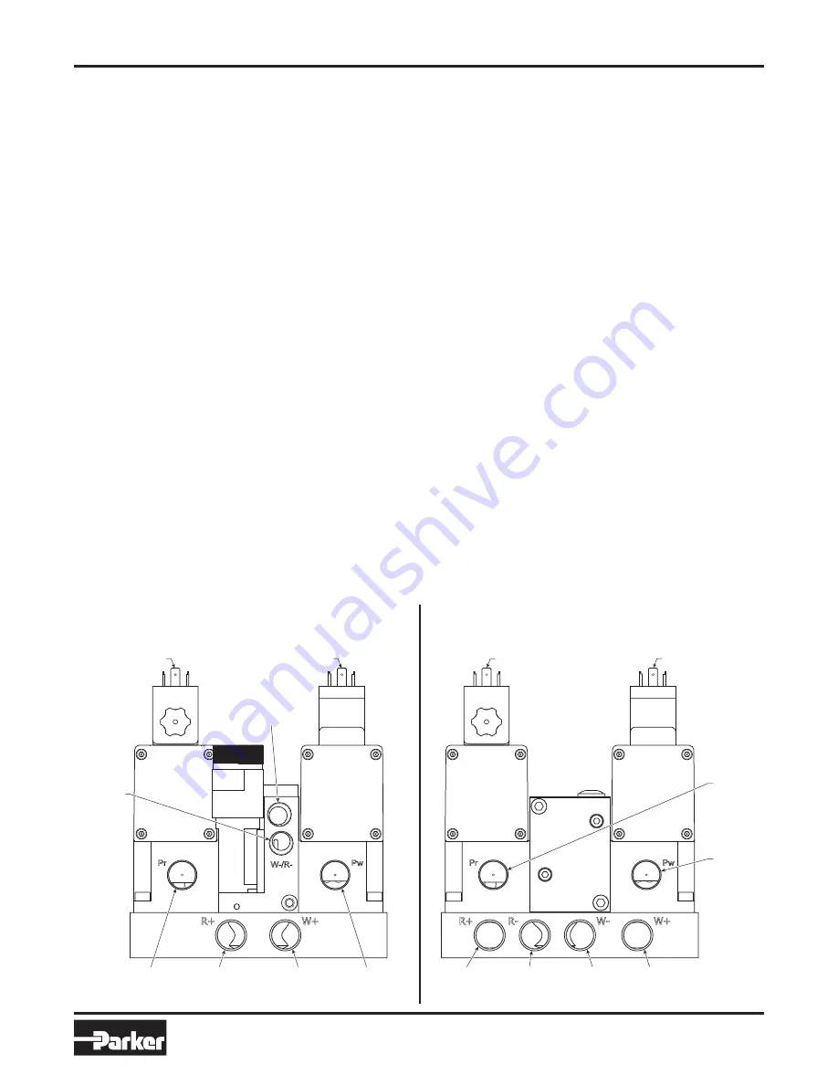
3 Ported Installation

4 Ported Installation

Weld Stroke

Connector(s)

Exhaust

High

Pressure

Inlet

Retract

Extend

Weld

Extend

Weld

Pressure

Inlet

Weld

Return

High

Pressure

Inlet

Weld

Pressure

Inlet

Weld Stroke

Connector(s)

Retract

(Pre-Stroke)

Connector(s)

Retract

(Pre-Stroke)

Connector(s)

Retract

Extend

Weld

Extend

Weld

Return

Retract

Return

Summary of Contents for WCS-SIF-01

Page 1: ...Pneumatic Spotwelding Control Systems Training Maintenance Manual WCS SIF 01 Training Maintenance Manual ISSUED November 2006 Supersedes June 2006 Pneumatic Division Richland Michigan 49083...

Page 2: ...ll lengthen time until it reaches a full 360 rotation which covers the complete timing range 3 The weld stroke valve is then energized using a selected weld schedule pressure The closure speed of the...

Page 3: ...ld cycle 4 Once the weld cycle is complete the weld stroke valve is de energized allowing the weld tips to open under full pressure 5 The retract pre stroke valve is then de energized allowing the wel...

Page 4: ...air supply and power on 9 Check for air leaks The weld cylinder should be in the home position completely open If not check that all air hoses are connected to the correct ports Verify that all solen...

Page 5: ...ause the flow control has been opened so much that all the air on the front side of the cylinder has exhausted before the tips fully close thus negating the low impact benefit of the system To guarant...

Page 6: ...nd dried to a dewpoint of 37 F 3 C lubricated or non lubricated Once lubricated air is applied this must be maintained Working Pressure 37 to 145 PSIG 2 5 to 10 bar WH Series Air Operated Quick Exhaus...

Page 7: ...oil F 24VDC M12 Connector X Without Valves N NPT G BSPP A 120VAC 22mm Coil B 120VAC 30mm Coil D 24VDC 22mm Coil E 24VDC 30mm Coil F 24VDC M12 Connector X Without Valves 4 Valve Block High Pressure Qui...

Page 8: ...k Quick Exhaust Mounted Cylinder Mount B Valve Block w Base Plate Air Operated High Flow Quick Exhaust G Valve Block w Base Plate High Pressure Quick Exhaust H Valve Block w Base Plate Solenoid Operat...

Page 9: ...lve Block w o Weld Stroke Valve K Valve Block ISO Manifold Mountable Plug In Air Operated High Flow Quick Exhaust L Valve Block ISO Manifold Mountable Plug In Solenoid Operated High Flow Quick Exhaust...

Page 10: ...st Lights Length Frequency Options Level H2 E WX H B L 49 C Ordering Information BOLD OPTIONS ARE MOST POPULAR 5599 1 Pilot Source Pilot Exhaust H 5 Port Vented 5599 1 Operator Function 2 Double Solen...

Page 11: ...Ford G General Motors Mounting Base Style Enclosures Wiring Engineering Factory Basic Series Port Size Lead Length Options Level Designator PS4111 55 A C P Engineering Level C Current Enclosures Lead...

Page 12: ...ion 1 and 2 for port 3 galley only Item Qty Part No 01 1 AAH2E002 02 1 H22VXHG0B9C Station 1 2 03 2 PS411157MCP Station 1 2 04 1 WPJ1XXXN Station 2 05 1 H2EVXHG0B9C Station 2 06 1 PS3632P Galley 3 Iso...

Page 13: ...ions 1 1 Station Manifold2 2 2 Station Manifold2 5 Single Subbase2 Basic Valve Manifold Engineering Series Series Protocol Subbase Stations Power I O Options Level S3 H2 D 2 D 0 C Engineering Level C...

Page 14: ...lb Torque 4 115 to 130 in lb Torque 4 85 to 100 in lb Torque 85 to 100 in lb Torque 6 8 Not Shown 9 Bore Lightly grease with provided lubricant Inspect for nicks scratches and surface imperfections I...

Page 15: ...8 5 50 1 5 4 9 7 3 0 9 58 7 10 19 136 5 35 9 0 35 50 7 00 1 7 3 5 01 10 4 0 8 1 10 44 8 1 76 8 1 10 58 8 31 11 5 0 45 81 5 3 1 9 5 1 16 15 0 59 33 1 30 B6 Series Dimensions mm inches 0 1 0 1 100 ED 1...

Page 16: ...er com pneumatics WH Series For 3 Ported Gun Dimensions mm inches 170 5 6 71 48 65 9 79 19 3 7 57 67 64 36 1 4 34 5 1 36 136 5 35 100 3 94 15 0 59 55 17 76 99 79 5 3 1 88 3 46 9 0 35 136 5 35 1 75 0 5...

Page 17: ...arker com pneumatics WH Series For 3 Ported Gun Dimensions mm inches 170 5 6 71 19 3 7 57 15 0 59 55 17 79 5 3 1 88 3 46 9 0 35 136 5 35 1 75 0 50 145 5 71 Pr Pw R R W W X I 12 X I 12 X I 14 1 0 PRESS...

Page 18: ...4 Ported Gun Dimensions WP ISO Size 2 Manifold Mountable X I 12 X 14 1 0 PRESS 58 8 109 5 4 31 31 5 1 4 16 1 0 63 63 48 3 1 6 88 8 3 49 46 5 1 83 146 7 5 78 80 7 3 18 187 5 7 38 08 7 8 WH ISO Size 2 M...

Page 19: ...Also verify feedback sensor is operating properly 4 Weld gun fires before tips are closed Adjust flow control so that weld tips close slower See Setup Instructions on page 5 Is sensor input in the PL...

Page 20: ...withstanding any charges paid by Buyer Unless otherwise agreed Seller shall have the right to alter discard or otherwise dispose of any special tooling or other property in its sole discretion at any...

Reviews: