


9
Parker Hannifin Corporation
TFP 5715-734UK.indd 24.06.22
2-Way Servo Proportional Valves
Series TFP
Operation Manual
Available Bolt Kits
Size
Ordering no.
Mounting bolt
Torque
TFP025
BK504
4 pcs. M12x100
108 Nm
TFP032
BK529
4 pcs. M16x100
264 Nm
TFP040
BK481
4 pcs. M20x110
517 Nm
TFP050
BK544
4 pcs. M20x130
517 Nm
TFP063
BK545
4 pcs. M30x140
1775 Nm
TFP080
BK546
8 pcs. M24x200
890 Nm
TFP100
BK547
8 pcs. M30x220
1775 Nm
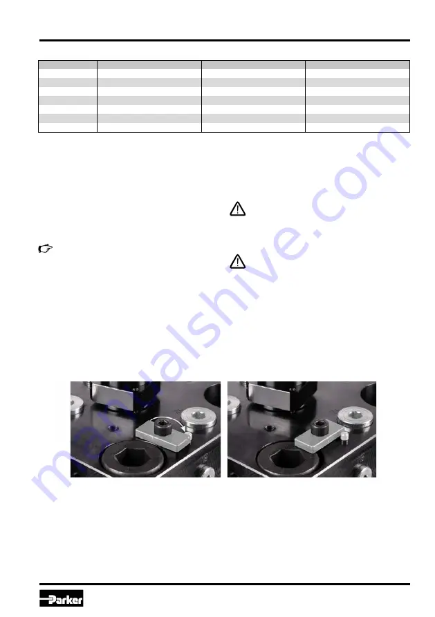
Disassembly
Use of disassembly aid (from nominal size NG50)
First loosen the two fixing screws without disas
-
sembly aid. Then loosen the two socket screws
SW6 (TFP050: the two ring bolts) with the disas-
sembly aids and turn the straps 90° against the
stop. Fix the socket screws/ring bolts again. Now
loosen the two remaining fixing screws alternate
-
ly. By turning them against the straps, the valve is
pulled out of the cavity.
Mounting
• Compare valve type (located on the name plate)
with part list resp. circuit diagram.
•
The valve may be mounted fix or movable in
any direction.
• Verify the mounting surface for the valve. Uneve-
ness of 0.01 mm/100 mm, surface finish of 6.3
µm are tolerable values.
Keep valve mounting surface and work envi-
ronment clean!
• Remove protection plate from the valve mounting
surface
• Check the proper position of the valve ports
and the O-rings.
• Mounting bolts: use property class 12.9, ISO 4762
Insufficient condition of the valve mounting
surface might create malfunction!
Incorrect mounting resp. bolt torque may
result in abrupt leakage of hydraulic fluid on
the valve ports.
Y-port has always to be tied directly and
separately to tank!
90°


