background image

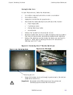
Chapter 3: Connecting to a Computer

Setting Up the Monitor


PHM/PM User Guide


3-5

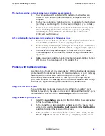
Step 2: Calibrating the Touchscreen 

Calibrating the touchscreen ensures that it is aligned with your display. The 

monitor’s touchscreen is calibrated before leaving Parker-CTC. However, 

you may need to recalibrate the touchscreen when you begin using the 

monitor for the first time or whenever the cursor does not follow the 

touches on the screen.

This section explains how to calibrate the Hampshire touchscreen driver 

under Windows 2000 and XP Professional.

To calibrate the touchscreen driver, complete the following steps:

1

Select Start Programs Hampshire TSHARC Control Panel. The 

control panel appears.

2

Follow the on screen instructions for selecting which monitor to 

calibrate. If you just have one monitor, select 1.

3

Select the Calibrate tab.

4

Click the center of where the arrows are pointing. The Calibration 

screen appears.

5

Touch the target where it appears on the screen, hold your finger 

there momentarily, and then release.The screen guides you through 

the Touch - Hold - Release process.

6

Repeat the process three more times in the other three corners of the 

screen. A test screen appears.

7

Move your finger across the monitor. The target should move with 

your finger. If so, the calibration was successful.

8

Select Accept.

9

On the control panel, select Apply and then select OK.
Note 

If the touchscreen still does not appear calibrated, and the 

cursor moves vertically when your finger moves horizontally 

on the screen or vice versa, the touchscreen cable may not 

be connected to the motherboard properly. Call a CTC 

customer service representative.

Step 3: Adjusting the Video Image

The monitor is equipped with an on screen display (OSD) that allows you to 

adjust the video image for the best possible picture. 

By default, the OSD is set to Auto which automatically adjusts all OSD 

settings to their optimum values. However, you can manually make 

adjustments by using the three buttons at the upper left side of the 

monitor. 

Summary of Contents for PHM 17" TFT

Page 1: ...The PHM PM User Guide July 2006 Parker CTC Automation 50 W TechneCenter Drive Milford Ohio 45150 Part A3 06717 01...

Page 2: ...or with the software protection key CTC s standard product warranty covers these items for 15 months from the date of shipment from CTC Exceptions appear below PowerStation backlight bulbs have a 90...

Page 3: ...lectrical Guidelines 2 3 Field Terminal Wiring Requirements 2 3 Temperature and Humidity Guidelines 2 4 Enclosure Guidelines 2 4 Accessing Ports and Other Controls 2 5 Radiated Emissions Guidelines 2...

Page 4: ...ng Common Problems 4 6 Problems with Display Operation 4 6 Problems with the Displayed Image 4 7 A Monitor Specifications A 1 Physical Specifications A 1 Display Specifications A 1 Environmental Speci...

Page 5: ...agram 2 9 Figure 3 1 Communication Ports on the Monitor 3 1 Figure 3 2 Power and Ground Ports 3 3 Figure 3 3 On Screen Display Menu 3 6 Figure 4 1 Removing the 17 Monitor Back Cover 4 3 Figure 4 2 Acc...

Page 6: ...ions A 1 Table A 3 Environmental Specifications A 2 Table A 4 Electrical Specifications A 3 Table A 5 European Community Immunity and Emission Standards A 3 Table A 6 Mechanical Testing Specifications...

Page 7: ...r 1 Introduction Presents an overview of this manual any other documentation provided with the monitor and how to contact customer support services Chapter 2 Installing the Monitor Explains how to sel...

Page 8: ...cross references Courier font Text to be entered from a keyboard Indicates two or more keyboard keys that must be pressed simultaneously For example Ctrl Alt Delete Note Alternative approaches or iss...

Page 9: ...mers including end users original equipment manufacturers OEM system integrators or distributors If you have a question about the monitor be sure to complete the following steps Check any release note...

Page 10: ...nitor package you are ready to unpack the unit and install it in a permanent location Follow the steps below to get started 1 Unpack the monitor and verify that you have received all of the components...

Page 11: ...section provides guidelines to follow when selecting a location Underwriters Laboratories Approval In order to obtain Underwriters Laboratories UL approval for your monitor installation the installati...

Page 12: ...is installed in a UL listed Type 4X enclosure Screen Chemical Resistance Properties HA210 Test Methods cosmetics OK naked eye total thickness gauge 710 micrometer pencil hardness 3H JIS 5400 adhesion...

Page 13: ...nd only at one end of the cable The monitor s electrical specifications are shown in the table below Make sure that your power source is compatible with the monitor before starting the unit The monito...

Page 14: ...r is operating inside an enclosure at temperature levels above its rated ambient temperature you must cool the enclosure You should allow a minimum of 2 inches between the inside of the enclosure and...

Page 15: ...ial and parallel port communication cables must be 100 braided shielded cable Radiated Emissions Guidelines This monitor has been tested to comply with international electromagnetic and emission stand...

Page 16: ...ge quality Refer to the CD that comes with the monitor for the depth and port dimensions of your monitor Use these dimensions to customize the mounting of your unit Important If using an external AC a...

Page 17: ...ard the bottom 3 Place the two adapter mounting clamps over the top and bottom of the adapter as shown in the illustration Align the holes in the clamps with the mounting holes in the back of the moni...

Page 18: ...the 15 monitor uses 8 clamps to mount in its enclosure while the 17 monitor uses 12 clamps To mount the monitor 1 Slide the monitor into the cutout from the front 2 Attach the mounting clamps with the...

Page 19: ...amp assemblies or you may damage the monitor However under tightening may not guarantee a Type 4 seal 6 Tighten the screws in a crosswise sequence to ensure a good seal and prevent damage Tightening t...

Page 20: ...s described in this chapter including how to connect the monitor to your computer how to prepare the monitor to work with your computer and how to read and adjust the on screen display OSD Connecting...

Page 21: ...or to the non display PowerStation or to another computer you are ready to start your system However before connecting power to your unit make sure that you have read and understood the electrical and...

Page 22: ...Figure 3 2 Warning Voltage input to the unit should be within the range specified in Electrical Specifications in Appendix A Figure 3 2 Power and Ground Ports 2 Connect the ground stud on the lower l...

Page 23: ...s installed in your PowerStation before it shipped If you are using your monitor with another computer or if your system becomes damaged you need to install or reinstall the touchscreen driver To inst...

Page 24: ...n appears 5 Touch the target where it appears on the screen hold your finger there momentarily and then release The screen guides you through the Touch Hold Release process 6 Repeat the process three...

Page 25: ...elected a setting this button enables you to decrease the value of the adjustment The first time that you change the monitor s resolution it attempts to automatically adjust the settings You may see a...

Page 26: ...t them each time you turn on the monitor Note If the OSD is turned on and then left unattended it automatically shuts off in 15 seconds Clock Phase Available selections Clock enables setting of the ho...

Page 27: ...ect Do not use any harsh material or powder such as steel wool or abrasive cleansers to clean the screen surface The surface is sensitive to scraping sharp blows or punctures Therefore keep screwdrive...

Page 28: ...ing or removing the backshell Do not touch any components of the monitor while the monitor is on Disconnect power before performing any internal maintenance or troubleshooting Only handle internal com...

Page 29: ...from its enclosure or arm 6 Place the monitor face down on a static dissipative mat in a location free from dirt and moisture and protected against static discharge 7 Remove the retaining nuts that s...

Page 30: ...d to perform Closing the Backshell 1 Carefully connect the touchscreen display and inverter board cables to their respective connectors see Figure 4 2 Be sure you orient the cables so that you do not...

Page 31: ...Figure 4 3 below Figure 4 3 Fuse Location on the Board 3 Use an ohm meter to see if the fuse is open or closed If open use a pair of needlenose pliers to lift the fuse from the fuse holder If closed t...

Page 32: ...blank 1 The PC may be in screen saver mode or video low power mode Touch the touchscreen be careful not to activate a tool within your HMI software move the mouse or press a keyboard key to restore t...

Page 33: ...ving the touchscreen replaced 4 Cables or wiring inside the monitor may be damaged Contact Parker CTC Product Technical Support at 513 248 1714 Problems with the Displayed Image A combination of incor...

Page 34: ...ontal Position selection to fine tune centering the image horizontally on the screen When video mode is changed the screen image shifts up or down The image s vertical position has not been optimized...

Page 35: ...teel bezel 13 3 x 16 8 x 3 1 338mm x 427mm x 77 9mm 15 Monitor with standard bezel 13 3 x 16 8 x 3 5 338mm x 427mm x 89 6mm 17 Monitor with standard bezel 15 7 x 18 x 3 2 399mm x 457mm x 80 5mm I O Po...

Page 36: ...ve vapors in order to minimize maintenance and repair costs 17 Monitor Color depth Up to 16 million colors Brightness 250 nits Backlight lifetime 50 000 hours Pixel format SXGA 1280 X 1024 Table A 3 E...

Page 37: ...power to the monitor from the equipment generating electrical noise Testing Specifications The monitor conforms to the emission standards for electronic equipment EN61000 6 2 2001 and EN55011 A2 2002...

Page 38: ...micrometer pencil hardness 3H JIS 5400 adhesion 100 100 1mm 100 grid cross hatch snap tape test steel wool pass rub VLT 92 2 BYK Gardner Hazegard Plus haze 8 63 BYK Gardner Hazegard Plus clarity 76 5...

Page 39: ...and unleaded Silicone based lubricant Alcohol ethyl methyl Automatic transmission fluid Caution Sustained exposure to brake fluid or Gunk brand degreaser can cause damage to monitor materials Touchsc...

Page 40: ...ignals The table below shows the video inputs from a host computer to the monitor Table A 8 Video Cable Specifications Video Cable Signals 1 Red 6 Green Shield 11 N C 2 Green 7 Blue Shield 12 DDC DATA...

Page 41: ...ge 2 1 for details 2 Mount the monitor See Mounting the Monitor in an Enclosure on page 2 6 for more information 3 Connect the monitor to a computer See Connecting to a Non display Computer on page B...

Page 42: ...your monitor a touchscreen driver was installed in your PowerStation before it shipped If you are using your monitor with another computer or if your system becomes damaged you need to install or rei...

Page 43: ...res that it is aligned with your display The monitor s touchscreen is calibrated before leaving Parker CTC However you may need to recalibrate the touchscreen when you begin using the monitor for the...

Page 44: ...F faceplate design 2 4 factory recall 3 7 fuse maintenance 4 2 part number 4 5 rating 2 3 A 3 replacing 4 5 G generic computer connecting to 3 2 getting started 1 4 H horizontal position 3 6 humidity...

Page 45: ...faceplate 2 2 physical A 1 testing A 3 starting your system 3 2 storage temperature 2 4 A 2 support contacting 1 4 services 1 3 surge immunity A 3 symbols caution 1 2 warning 1 2 T temperature guideli...

Reviews: