4
www.parker.com/euro_pneumatic
5. Assembly Instructions
Perform all assembly, installation, maintenance and
repair work outside of the Ex-area.
5.1 Prior to Installation
The air motor should only be installed if:
• the details of the motor tag correspond with the details
of the potentially explosive athmosphere of use (design
group, design category, Ex-area, temperature class,
maximum surface temperature).
• it is undamaged.
• it was verified that no explosive atmospheres, oils,
acids, gases, steams or radiation, occurred during
installation.
5.2 Pre-Installation
Drive shafts and flange areas should always be free from
anticorrosive solvents, dirt or other agents. Solvents
should not be allowed to penetrate the gear seal ring –
this may cause material damage!
To avoid a swelling of the seal rings and damage to
internal parts of the air motor, use only solvents approved
by Parker (such as HAKU 1025-810-1 cold cleaner). Seal
material: NBR/FKM
5.3 Operating Pressure and Temperature Range
Operating Pressure
Maximum operating pressure: 6 bar / 85 PSI
Temperature Range
Ambient temperature at standard operating
(outside Ex-area): -20°C to +110°C
Ambient temperature for use in Ex-area: -20 °C to + 40 °C
Compressed Air Temperature
The temperature of the compressed air used may not
exceed the ambient temperature requirements.
If ambient temperatures are different, please contact
Parker.
5.4 Installation Instructions
Important Notes for Installation of Motor
• Install the motor according to the dimension sheet
(see chapter 5.6).
• The air motor may be installed in any orientation.
• Non-reversible air motors have a right or left rotational
direction (as seen from air inlet in the direction to the
drive.
• Use only mounting brackets having a sufficient size.
• Use only the implemented mounting holes to fixture the
air motor.
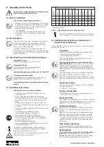
• Observe the tightening torques for the mounting screws
(see table 1).
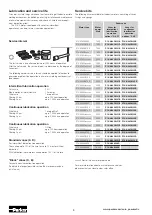
• A maintenance unit should be installed
(see illustration „Diagram“ in chapter 5.7).
• Be especially careful with all rotating parts.
• Do not install a belt pulley, clutch or pinion to the
shaft-end, using ham-mer blows; this will damage
gears, housing and shaft.
• Use an extractor for disassembly.
• Do not exceed the permissible radial and axial forces of
the shaft (see chapter 4.2).
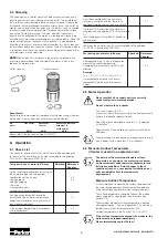
Attachment of the drive element will be simplified if a
lubricant is applied or when heated-up for a moment –
prior to installation (to 80°C to 100°C).
Drive attachments, such as a belt pulley, clutch, etc. have
to be covered by a contact guard.
8.8 0.72 1.28 2.9 5.75 9.9 24 48 83 132 200 275 390
10.9 1.02 1.8 4.1 8.1 14 34 67 117 185 285 390 550
12.9 1.21 2.15 4.95 9.7 16.5 40 81 140 220 340 470 660
70* 0.46 0.82 1.9 3.7 6.4 15.3 31 52 83 126 174 245
M 2.5
M 3
M 4
M 5
M 6
M 8
M 10
M 12
M 14
M 16
M 18
M 20
Pr
operty
Class
Tightening torque (Nm) for thread ...
Use screws of property class (min.) 8.8 or 70 for stainless
screws in order to mount the air motor onto your machine.
* for stainless screws
Table 1 – Tightening torques for mounting screws
5.5 Additional Instructions for Installation in an
Explosive Hazardous Area
Grounding
The air motor must be grounded, for example by using
• an air-supply line made of metal or
• an electrically conductive hose.
The resistance between motor and ground has to be
measured (requirement: <10
6
Ω).
Only use drive attachments that correspond to gui-
deline 2014/34/EU.
Only use belts in the Ex-area, which
correspond to the guideline 2014/34/EU (among others,
items to watch is the belts electric conductivity and the
correct belt-tension, since either may generate heat due to
slippage).
The explosion-proof air motors correspond to the design
requirements of the design group II, category 2 GD
(explosive atmosphere consisting of gas and dust). Those
motors are suited for the installation into Zone 1 and Zone
21.
Temperature Class
The air motors of group II, category 2 GD are suitable for
the temperature class:
• T3 (for all P1V-A air motors)
Surface Temperature
This corresponds to a maximum surface temperature of:
• 200°C (for all P1V-A air motors)
Protection Class
All air motors must correspond – for a minimum – with the
standard EN 60529 of the protection class IP 54. They are
designed for the use in dusty or damp environments.
Ambient Conditions
Make sure that the air motor is sufficiently ventilated and
that there is no additional warming source (such as a
clutch).
Open inlet- and exhaust ports are not permissible. Those
type of ports have to be closed, using either a sintered-
metal filter (optional equipment) or an airline. If an airline
is installed to any of the open ports (without the use of a
sintered-metal filter), then they have to be guided out of
the Ex-area.
Drive Power and Torque
Do not exceed either the maximum permissible drive
power, or the maximum allowable radial and axial forces.
Braking Mode
The air motors may not be used in a braking mode in
the Ex-area.
A braking mode is when the motor is
operated opposite to the turn-direction of the air-supply;
this will have the motor operate as a compressor.
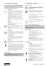
Always follow the safety instructions of chapter 2.5 while installing an air
motor into an Ex-area.


