IQ-200 User’s Manual
17
Parker Hannifin Corporation
Hydraulic Filter Division
Metamora, OH
Installation and Operation
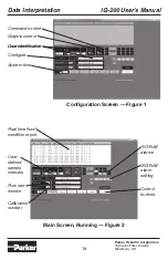
The operation controls on
the second page include:
CHANNEL
This list box permits setting
which channels are monitored by channel
number when USER is selected in the
Graphic Control box on page one. If ISO is
selected in the Graphic Control box on page
one, then this control will be dimmed.
This is a pushbutton control to print
an IQ200 test report consisting of the ten
lines of data currently appearing in the text
box on the first page and the graph from the
second page, along with the User supplied
identification (see example page 16)
CLEAR
This pushbutton clears the graph.
CLOSE
This pushbutton closes the graph
page and returns to page one.
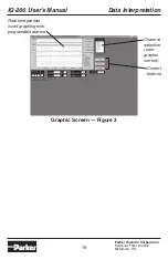
The Graph displays particle counts for the
channels selected and limit lines. The ISO
text boxes the NAS text box and the LIMIT
text boxes show those limits set on page one.
The FLOW text box and the CALIBRATION
text box display those values.
MOUNTING and HARDWARE
Mounting:
The unit should be mounted to a backplate or
frame using four (4) 3/8"-16 bolts. The holes
on the back of the filter are 3" center to center
in both the horizontal and vertical direction.
The unit shoud be mounted in a way to leave
the top cap of the filter accessible
Parts Required for Installation:
• Fluid connectors capable of mating to
SAE-4 female.
• Hose or tubing.
• Valve to “meter-out” flow.
• 12-24 VDC @ One Amp, power supply.
• Brad Harrison Micro-Change cable to
mate with 7R5A06A19A120 for serial
communications
(see serial cable wiring diagram)
• Brad Harrison Micro-Change cable to
mate with 7R4A06A19A120
for 12-24
VDC power supply
(see power cable wiring diagram)
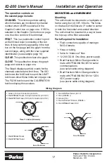
Wiring Diagram
1. Green (To 9 pin Connector pin 5 9.5)
2. Red W/Black Tracer (To 9 pin Connector pin 3 9.3)
3. Red W/White Tracer (To 9 pin Connector pin 2 9.2)
1. Red W/Black Tracer
2. Red W/White Tracer
3
2
1
TRANSMIT
RECEIVE
GROUND
Three Pin Serial (Obsolete)
3
2
4
NOT USED
COMMON
NOT USED
Four Pin Power
24 VDC
1
1. Red W/
White
Tracer (to 9.2)
2. Red (RS485 +)
3. Green (9.5)
4. Red w/Yellow TRracer (RS485 -)
5. Red W/Black Tracer (9.3)
Five Pin Serial
RS 485 (+)
TRANSMIT
RS485 (-)
GROUND
5
1
2
3
4
RECEIVE


