English
5 / 8
ICEP040-060
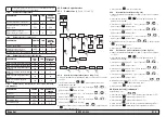
4.4.2 Temperature
control
PARAMETER
CODE
TYPE
DEFAULT
Temperature control set point
SEt
D
--
Temperature control set point
“
CPt
=
On
”
SEt
D
20.0
Temperature control differential
(NOT visible with code “
CPt
=
On
”)
dIFI
D
4.0
4.4.3 Compressor
parameters
PARAMETER
CODE
TYPE
DEFAULT
Minimum `On’ time.
dAS
F
2
Minimum time between two com-
pressor switch-ons.
dES
F
5
Compressor hour counter 1
CIH
D
0
4.4.4
B1, B2, B3 sensor parameters
PARAMETER
CODE
TYPE
DEFAULT
High temperature alarm (water)
HA1
D
60
Low temperature alarm (water)
LA1
U
-20
High temperature alarm (eva-
porator)
HA2
U
60
Low temperature alarm (eva-
porator)
LA2
U
3
High temperature alarm (am-
bient)
HA3
U
60
Low temperature alarm (am-
bient)
LA3
U
-20
4.4.5
Differential dinamic temperature parameter
PARAMETER
CODE
TYPE
DEFAULT
Parameter
(5'
U
OFF
Differential
GW+$
U
5
Water minimum set
G0,Q
U
10
Water maximum set
'0$
U
25
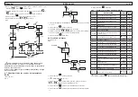
4.5 Change parameters
4.5.1 Parameter
(
SEt
/
dIFI
/
dEF
)
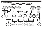
Fig.2
set
set
set
set
set
PAr
esc
set
Y
Y
set
Y
P_nA
tEr
CnP
r9E
Y
Y
PbI
Y
Y
Ar9
Y
HA1
Y
C1H
Y
Y
C1H2
SEt
Y
diFI
CF30
CF31
CF32
dEF
Y
Y
Y
Y
Y
rE
Y
4.5.2
Water temperature setting (see fi g.1/2)
1. Turn the main swicth (QS) to “ON” and wait for the “
OFF
” visualiza-
tion.
2. Press the buttons “
esc
” “
set
” together to enter on the parameter
type “
D”
.
3. Select the parameter “
PAr
”using “
”and “
” buttons and
press the button “
set
” to enter.
4. Select the parameter “
tEr
”using “
”and “
” buttons and
press the button “
set
” to enter.
5. Select the parameter “
SEt
”using “
”and “
” buttons and
press the button “
set
” to enter.
6. Change the value using “
”and “
” buttons and press the
button “
set
” to confi rm and exit.
7. Press the button “
esc
” three times to exit.
4.5.3
Differential setting (see fi g.1/2)
1.Turn the main swicth (QS) to “ON” and wait for the “
OFF
” visualiza-
tion.
2.Press the buttons “
esc
” “
set
” together to enter on the parameter
type “
D”
3.Select the parameter “
PAr
”using “
”and “
” buttons and
press the button “
set
” to enter.
4. Select the parameter “
tEr
”using “
”and “
” buttons and
press the button “
set
” to enter.
5. Select the parameter “
dIFI
”using “
”and “
” buttons and
press the button “
set
” to enter.
6. Change the value using “
”and “
” buttons and press the
button “
set
” to confi rm and exit.
7. Press the button “
esc
” three times to exit.
4.5.4
Restore default parameters (see fi g.1/2)
1.Turn the main swicth (QS) to “ON” and wait for the “
OFF
” visualiza-
tion.
2.Press the buttons “
esc
” “
set
” together to enter on the parameter
type “
D”
3.Select the parameter “
PAr
”using “
”and “
” buttons and
press the button “
set
” to enter.
4. Select the parameter “
P_nA
”using “
”and “
” buttons and
press the button “
set
” to enter.
5. Select the parameter “
dEF
”using “
”and “
” buttons and
press the button “
set
” to enter.
6. Change the value “
OFF
” to “
On
” using “
”and “
” buttons
and press the button “
set
” to confi rm and exit.
7. Press the button “
esc
” three times to exit.
Summary of Contents for Hyperchill Plus ICEP040
Page 2: ......
Page 130: ...8 8 ICEP040 060 6...
Page 138: ...8 8 ICEP040 060 6...
Page 148: ......
Page 168: ...7 6 Circuit Diagram ICEP040 060 air 19 ICEP040 060...
Page 169: ...Circuit Diagram ICEP040 060 water 20 ICEP040 060...
Page 170: ...7 7 Wiring diagram ICEP040 060 21 ICEP040 060 Sheet 1 12...
Page 171: ...7 7 Wiring diagram ICEP040 060 22 ICEP040 060 Sheet 2 12...
Page 172: ...7 7 Wiring diagram ICEP040 060 23 ICEP040 060 Sheet 3 12...
Page 173: ...7 7 Wiring diagram ICEP040 060 24 ICEP040 060 Sheet 4 12...
Page 174: ...7 7 Wiring diagram ICEP040 060 25 ICEP040 060 Sheet 5 12...
Page 175: ...7 7 Wiring diagram ICEP040 060 26 ICEP040 060 Sheet 6 12...
Page 176: ...7 7 Wiring diagram ICEP040 060 27 ICEP040 060 Sheet 7 12...
Page 177: ...7 7 Wiring diagram ICEP040 060 28 ICEP040 060 Sheet 8 12...
Page 178: ...7 7 Wiring diagram ICEP040 060 29 ICEP040 060 Sheet 9 12...
Page 179: ...7 7 Wiring diagram ICEP040 060 30 ICEP040 060 Sheet 10 12...
Page 180: ...7 7 Wiring diagram ICEP040 060 31 ICEP040 060 Sheet 11 12...
Page 181: ...7 7 Wiring diagram ICEP040 060 32 ICEP040 060 Sheet 12 12...
Page 182: ......


