

P
P
P
OW
E
R
OW
E
R
OW
E
R
O
O
O
N
N
N
R
E F E R EN C E
S
EQ UEN C ING
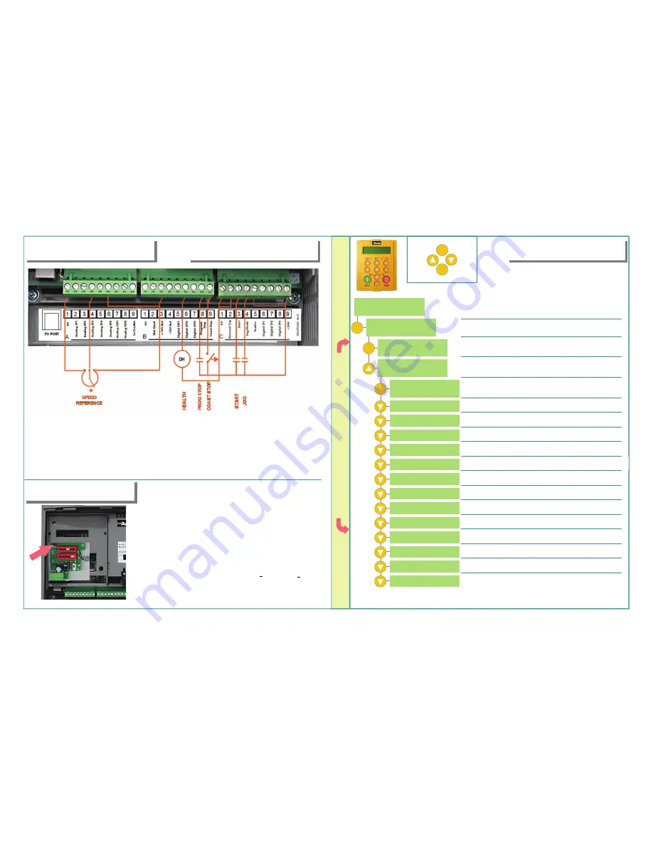
•
Speed potentiometer across A1
(low), B3(high), A4(wiper) OR
•
External 2-wire speed reference
between A1(-) and A4(+)
•
Jumper A6 to B3
•
E-Stop relay n.o. contact between B8, C9
•
E-Stop relay n.o. TDD contact between B9, C9
•
Jumper C1 and C2 if no external trip contact
•
Jumper C5 and C9 for internal enable contact
•
Start contact between C3 and C9
•
Jog contact between C4 and C9
•
Health relay coil (24V) between B6(+) and C1(-)
•
Armature Voltage is the default speed feedback
mode and does not require a feedback card.
•
Four feedback cards are available. Analog Tach,
encoder, acrylic microtach and glass microtach.
•
Select the correct feedback card. Install it on the
feedback header, shown by the arrow in the figure.
Ensure all standoffs are securely snapped in place
•
On the analog tach card, set switch settings in Units,
Tens and Hundred, corresponding to tachometer
output voltage at maximum speed
•
DC Analog Tach: G3(+), G4(-). Set switch to DC
•
AC Analog Tach: G1, G2. Set switch to AC
•
Encoder: E1=0V, E2=+, E3,E4=A, A, E5,E6=B, B
•
Microtach: C1=0V, C9=24V, F1=fiberoptic receive
S
P E E D
F
E E D BAC K
C
A L I B RAT I O N
All calibration is done in software, through
the keypad
.
M
E
ESCAPE ONE LEVEL
ENTER MENU
SCROLL
UP
SCROLL
DOWN
The
DC
590+ can also be calibrated using the programming tool software
.
This is the power-up welcome screen
DIGITAL DC DRIVE
DC 4Q 34A
MENU LEVEL
DIAGNOSTICS
MENU LEVEL
CONFIGURE DRIVE
NOM MOTOR VOLTS
CONFIGURE DRIVE
CONFIGURE ENABLE
ARMATURE CURRENT
FIELD CURRENT
FLD. CTRL MODE
FLD. VOLTS RATIO
MAIN CURR.LIMIT
AUTOTUNE
SPEED FBK SELECT
ENCODER LINES
ENCODER RPM
ENCODER SIGN
SPD. INT TIME
SPD. PROP GAIN
DC 4Q 34A
MENU LEVEL
Press M. You are in MENU LEVEL, at DIAGNOSTICS
Press the M key to get to MENU LEVEL
Up arrow to get to CONFIGURE DRIVE menu
Press M and up arrow to ENABLE drive configuration
All 7 LEDs blink in Configuration mode. Press E when done
Enter rated motor armature current
Toggle between voltage and current modes
Enter desired current limit setting. Usually 100%
Change the polarity of the encoder signal
Speed loop integral gain
Speed loop proportional gain
Using the Up & Down arrows, enter rated motor voltage
Enter rated field current. Skip if field is in Voltage mode
If in voltage mode: Ratio = (field volts/AC supply)*100
Example: For a 300V field and 460V supply: Ratio = 300/460*100 = 65%
Leave this OFF. Autotune after calibration is complete
Choose from Armature Volts/Analog Tach/Encoder
Enter the pulses per rev. rating of the encoder
Enter the max speed here. Corresponds to 100% speed
•
Set CONFIGURE ENABLE to DISABLE. The drive will display “CALIBRATING”
•
Under MENU LEVEL/PARAMETER SAVE, press the M and UP to save your settings
M
M
M


