Parker Compax3 Series Installation Manual Download Page 58

Technical Data

56

192-120102 N7 - February 2004

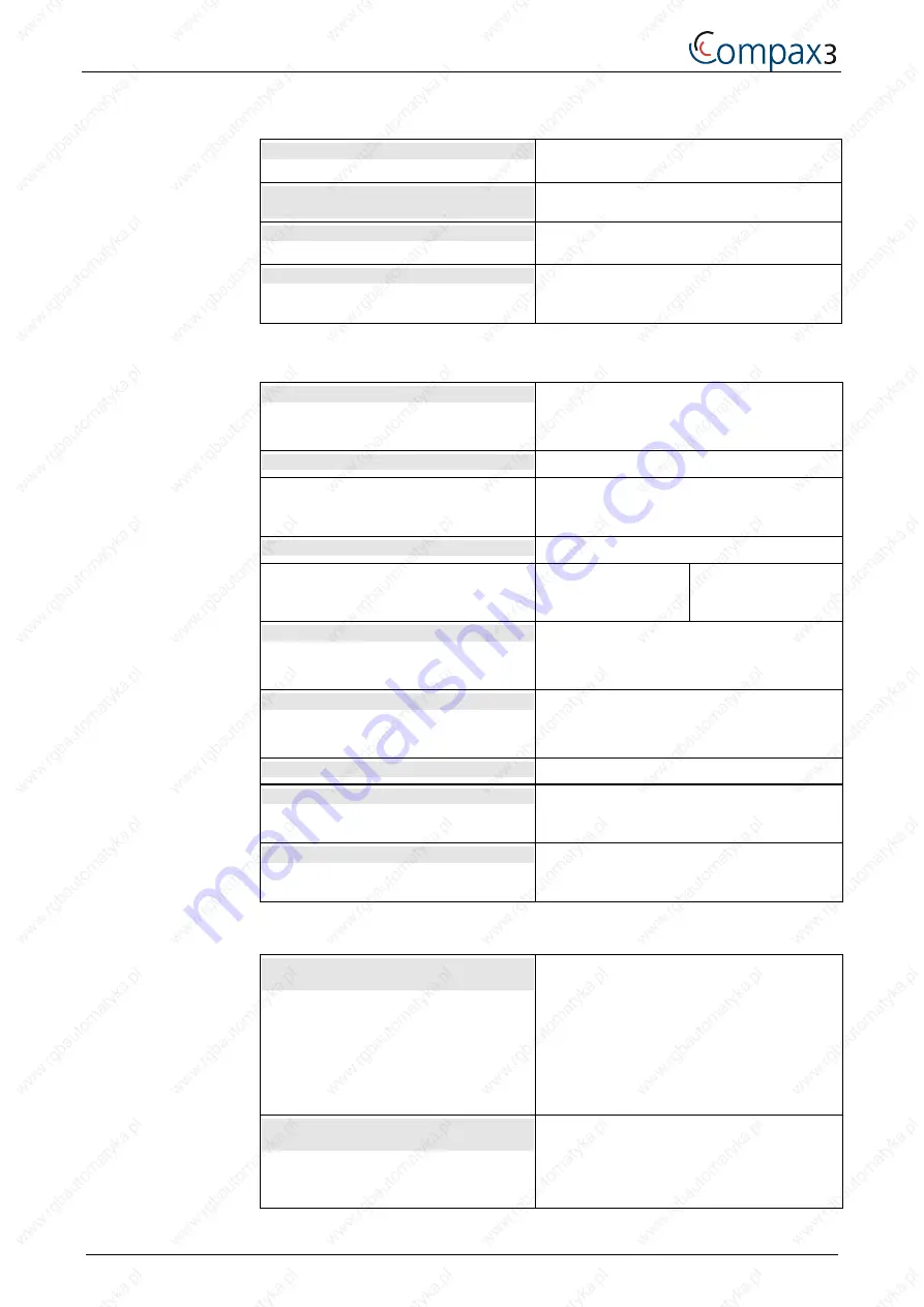
Insulation requirements

Protection class

Protection class I according to EN 50 178 (VDE
0160 part 1)

Protection against human contact with
dangerous voltages

According to DIN VDE 0106, part 100

Overvoltage category

Voltage class III according to HD 625 (VDE
0110-1)

Degree of contamination

Degree of contamination 2 according to HD 625
(VDE 0110 part 1) and EN 50 178 (VDE 0160
part 1)

Ambient conditions

General ambient conditions

In accordance with 

EN 60 721-3-1 to 3-3

Climate (temperature/humidity/barometric
pressure): Class 3K3

Permissible ambient temperature:

Operation
Storage
Transport

0 to +45 C

Class 3K3

–25 to +70 C

Class 2K3

–25 to +70 C

Class 2K3

 Tolerated humidity:

No condensation

Operation
Storage
Transport

<= 85% Class 3K3
<= 95% Class 2K3
<= 95% Class 2K3

(Relative humidity)

Elevation of operating site

<=1000m above sea level for 100%  load
ratings

Please inquire for greater elevations

Cooling mode

Compax3 S025 V2 ... S150 V4: convection

Compax3 S300 V4: force-ventilation via fan in
the heat dissipator

Sealing

IP20 protection class according to EN 60 529

EMC interference emission

Limit values according to EN 61 800-3, Class ‘A‘
with integrated mains filter for up to 10 m cable
length, otherwise with external mains filter

EMC disturbance immunity

Limit values for industrial utilization according to
EN 61 800-3 (includes EN 50 081-2 and EN 50
082-2)

EC directives and harmonised EC norms

EC low voltage directive
73/23/EEC and RL 93/68/EEC

EN 50 178, General industrial safety norm

Equipping electric power systems with
electronic operating equipment

HD 625, general electrical safety

Insulation principles for electrical operating
equipment

EN 60 204-1, Machinery norm

, partly applied

EC-EMC directive
89/336/EEC

EN 61 800-3, EMC norm

Product standard for variable speed drives

EN 50 081-2 ... 50 082-2, EN 61 000-4-2 ...61
000-4-5

Summary of Contents for Compax3 Series

Page 1: ...AWNA Jana Dlugosza 2 6 Street 51 162 Wrocław Poland biuro rgbelektronika pl 48 71 325 15 05 www rgbautomatyka pl www rgbelektronika pl DATASHEET www rgbautomatyka pl www rgbelektronika pl OTHER SYMBOLS C3S025V2 F10 I20 T30 M00 PARKER HANNIFIN ...

Page 2: ...ed with a wide variety of tools and having several testing stands at their disposal are a guarantee of the highest quality service OUR SERVICES ENCODERS SERVO DRIVERS LINEAR ENCODERS SERVO AMPLIFIERS CNC MACHINES MOTORS POWER SUPPLIERS OPERATOR PANELS CNC CONTROLS INDUSTRIAL COMPUTERS PLC SYSTEMS Repair this product with RGB ELEKTRONIKA ORDER A DIAGNOSIS Buy this product at RGB AUTOMATYKA BUY ...

Page 3: ...us at the time of printing Compax3 Installation Manual Single axis devices Paper version 192 120102 N7 February 2004 Release 1 2004 as from firmware V2 03 890 130001 Compax3 Unterlagen Software user guides tools manuels tools Compax3 CD english deutsch français Compax3 Installations Handbuch deutsch Compax3 Installation Manual english Manuel technique Compax3 français ...

Page 4: ...in plc Electromechanical Automation 21 Balena Close Poole Dorset England BH17 DX UK Tel 44 0 1202 69 9000 Fax 44 0 1202 69 5750 E mail sales digiplan parker com mailto sales digiplan parker com Internet www parker eme com http www parker eme com Parker Hannifin S p A Electromechanical Automation Via Gounod 1 I 20092 Cinisello Balsamo MI Italy Tel 39 0 2660 12459 Fax 39 0 2660 12808 E mail sales sb...

Page 5: ...D also contains additional help files as well as manuals in PDF format that can be printed to compile a complete hardcopy version of the respective manual Please note that the help files and the manuals are associated with defined device and software versions The catalogs supplied provide an overview of and information on the Compax3 device series The Adobe Acrobat Reader is also included on the C...

Page 6: ...llation 350 MB before installation 200 MB after installation Super VGA Monitor with a resolution of at least 800 x 600 setting small fonts you do not need administrator authorization for an update version Your PC is connected with Compax3 over an RS232 cable SSK1 COM interface on the PC based on X10 Compax3 Start the Compax3 ServoManager and make the setting for the selected interface in the menu ...

Page 7: ...ation 10 2 3 2 2 C3 MotorManager configuration of almost any motor 11 2 3 2 3 C3 IEC61131 3 Debugger 11 2 3 2 4 CoDeSys IEC61131 3 development tool 11 2 3 2 5 CamEditor cam creation for C3 T40 11 2 3 3 Complements corrections in manual and online help 11 2 4 Safety Instructions 12 2 4 1 General hazards 12 2 4 2 Safety conscious working 12 2 4 3 Special safety instructions 13 2 5 Warranty condition...

Page 8: ... 2 Input wiring of digital inputs 28 3 2 11 Resolver Feedback connector X13 29 3 3 Installation and dimensions Compax3 30 3 3 1 Installation and dimensions of Compax3 S0xx V2 30 3 3 2 Installation and dimensions of Compax3 S038 and S075 V4 31 3 3 3 Installation and dimensions of Compax3 S150 V4 32 3 3 4 Installation and dimensions of Compax3 S300 V4 33 3 4 Safety function safe standstill 34 3 4 1 ...

Page 9: ...ty instructions 12 Warranty conditions 13 Conditions of utilization 14 Manufacturer s declaration of conformity 17 2 1 Device assignment This manual applies to the following devices Compax3 S025 V2 supplement Compax3 S063 V2 supplement Compax3 S038 V4 supplement Compax3 S075 V4 supplement Compax3 S150 V4 supplement Compax3 S300 V4 supplement 2 Introduction ...

Page 10: ...in in 100mA 025 2 5A V2 230VAC single phase V4 400VAC three phase 3 Unique number of the particular device 4 Nominal power supply voltage of the device 5 Designation of the feedback system F10 Resolver F11 SinCos Single or Multiturn F12 Feedback module for direct drives 6 Device interface I10 Analog Step Direction and Encoder Input I11 Digital inputs outputs I20 Profibus DP I21 CANopen 7 Correspon...

Page 11: ...s The feedback module F12 supports the following feedback systems Distance coding with 1VSS Interface Distance coding with RS422 Interface Encoder 2 3 1 2 Switching frequency of the power output stage can be set The switching frequency of the power output stage can be increased if necessary This helps mainly to reduce motor sounds Please note that power output stage losses increase with rising swi...

Page 12: ... read about the following in this chapter C3 ServoManager configuring Compax3 setup and optimization 10 C3 MotorManager configuration of almost any motors 11 C3 IEC61131 3 Debugger 11 CoDeSys IEC61131 3 development tool 11 CamEditor Cam creation for C3 T40 11 2 3 2 1 C3 ServoManager configuring Compax3 setup and optimization A modified recipe array can be loaded separately without complete downloa...

Page 13: ...rom 10kgmm2 to 1kgmm2 Configuration of rotatory motors with analog hall sensors was completed 2 3 2 3 C3 IEC61131 3 Debugger Forcing of the inputs for T30 and T40 is possible 2 3 2 4 CoDeSys IEC61131 3 development tool New CoDeSys version 2 3 2 6 2 3 2 5 CamEditor cam creation for C3 T40 2 3 3 Complements corrections in manual and online help New structure of the manual All technology functions ar...

Page 14: ...purpose 2 4 2 Safety conscious working This device may be operated only by qualified personnel Qualified personnel in the sense of these operating instructions consists of Persons who by virtue to their training experience and instruction and their knowledge of pertinent norms specifications accident prevention regulations and operational relationships have been authorized by the officer responsib...

Page 15: ...inear drives present are mounted securely Check that all live terminals are secured against contact Fatal voltage levels of to 750V occur 2 5 Warranty conditions The device must not be opened Do not make any modifications to the device except for those described in the manual Make connections to the inputs outputs and interfaces only in the manner described in the manual When installing the device...

Page 16: ...ng mains filters are available for independent utilization Device Compax3 Order No Condition S0xx V2 NFI01 01 Only for motor lines longer than 10m S038 S075 S150 V4 NFI01 02 Only for motor lines longer than 10m S300 NFI01 03 Only for motor lines longer than 10m Industrial area limit values in accordance with EN 61800 3 Longer motor cable lengths are possible in industrial areas without a mains pow...

Page 17: ... resistance and low inductance Never mount the filter housing and the device on paint coated surfaces Signal lines and power lines should be installed as far apart as possible Signal leads should never pass close to excessive sources of interference motors transformers etc Make sure to use only the accessories recommended by Parker Connect all cable shields at both ends ensuring large contact area...

Page 18: ...f at least 60 C Maximum ambient temperature 45 C Suitable for use on a circuit capable of delivering not more than 500 rms symmetrical amperes 400 volts maximum ATTENTION Danger of electric shock Discharge time of the bus capacitator is 5 minutes The drive provides internal motor overload protection This must be set so that 200 of the nominal motor current are not exceeded Cable cross sections Mai...

Page 19: ...ve been designed and manufactured in conformity with the essential requirements of the Standards and other Normative Documents listed in the following Applied harmonized Standards especially Electromagnetic Compatibility EN 61 800 3 VDE 0160 part 100 EMC product standard for adjustable speed electrical power drive systems including special testing procedures Safety EN 50 178 VDE 0160 Electronic eq...

Page 20: ...nt Compax3 19 Installation and dimensions Compax3 30 Safety function safe standstill 34 3 1 State of delivery Compax3 is delivered without configuration After switching on the 25VDC supply the red LED is flashing while the green LED is dark Please configure the device with the help of the Windows Software Compax3 ServoManager 3 Compax3 device description ...

Page 21: ...pply plug X2 for 400VAC devices 22 Motor Motor brake plug X3 23 Control voltage 24 VDC enable plug X4 24 RS 232 RS485 interface plug X10 25 Analog Encoder plug X11 26 Digital inputs outputs plug X12 27 Resolver Feedback plug X13 29 Connection assignment based on the example of Compax3 S025 V2 Always switch devices off before wiring them Dangerous voltages are still present until 5 minutes after sw...

Page 22: ...shing off Axis without current excitation off Flashes slowly Power supplied to axis commutation calibration running off Flashes quickly Axis with current excitation off on Axis in fault status fault present on off 3 2 2 Power supply plug X1 for 230VAC devices PIN Description 1 L 2 N 3 PE Mains connection Compax3 S0xx V2 Controller type S025 V2 S063 V2 Mains voltage Single phase 230VAC 10 80 230VAC...

Page 23: ...eff 22Aeff Maximum fuse rating per device 10A automatic circuit breaker K 16 A automatic circuit breaker K 25A automatic circuit breaker K Always switch devices off before wiring them Dangerous voltages are still present until 5 minutes after switching off the power supply 3 2 4 Ballast resistor high voltage supply plug X2 for 230VAC devices PIN Description 1 Ballast resistor 2 Ballast resistor 3 ...

Page 24: ...cted 3 2 5 Ballast resistor high voltage supply plug X2 for 400VAC devices PIN Description 1 Ballast resistor 2 Ballast resistor 3 PE 4 DC high voltage supply 5 DC high voltage supply Caution The connector assignment of X2 is changed Please note the screen printing on the front plate of the device this is valid Compax3 Sxxx V4 brake operation Controller type S038 V4 S075 V4 S150 V4 S300 V4 Capacit...

Page 25: ...ase of non compliance with the following instructions the device may be destroyed You can only connect two similar devices same power supply same rated currents Connected devices must always be fed separately via the AC power supply 3 2 6 Motor Motor brake plug X3 PIN Description 1 U motor 2 V motor 3 W motor 4 PE motor 5 BR Motor holding brake 6 BR Motor holding brake Screening connection of the ...

Page 26: ...from Pin 1 Safe standstill X4 3 0V For implementation of the Safe standstill safety feature in accordance with the protection against unexpected start up described in EN1037 Please refer to the respective chapter see on page 34 can be found in the paper version installation manual Compax3 with the circuitry examples The energy supply to the drive is reliably shut off the motor has no torque A rela...

Page 27: ...1 5V RS485 RS232 PIN X10 RS232 Sub D 1 Enable RS232 0V 2 RxD 3 TxD 4 DTR 5 GND 6 DSR 7 RTS 8 CTS 9 5V RS485 2 wire PIN X10 RS485 two wire Sub D Pin 1 and 9 jumpered externally 1 Enable RS485 5V 2 res 3 TxD_RxD 4 res 5 GND 6 res 7 TxD_RxD 8 res 9 5V RS485 4 wire PIN X10 RS485 four wire Sub D Pin 1 and 9 jumpered externally 1 Enable RS485 5V 2 RxD 3 TxD 4 res 5 GND 6 res 7 TxD 8 RxD 9 5V ...

Page 28: ...s RS422 5V level A encoder input emulation 8 Input direction RS422 5V level B encoder input emulation 9 Ain0 analogue input 14 bit 10 Ain1 analogue input 14 bit 11 Ain0 analogue input 14 bit 12 Input direction RS422 5V level B encoder input emulation 13 Reserved N Encoder simulation 14 Reserved N Encoder simulation 15 GND The exact assignment depends on the the device type You will find the descri...

Page 29: ...100mA 4 O2 Output 2 max 100mA 5 O3 Output 3 max 100mA 6 I0 Input 0 7 I1 Input 1 8 I2 Input 2 9 I3 Input 3 10 I4 Input 4 11 I 24V input for the digital outputs Pins 2 to 5 12 I5 Input 5 13 I6 Input 6 14 I7 Input 7 15 O Gnd 24 V All inputs and outputs have 24V level Maximum capacitive load on the outputs 50 nF max 4 Compax3 inputs The exact assignment depends on the the device type You will find the...

Page 30: ...cuit proof a short circuit generates an error F1 Delayed action fuse F2 Quick action electronic fuse can be reset by switching the 24VDC supply off and on again 3 2 10 2 Input wiring of digital inputs 24V 0V 100KΩ X12 1 X12 6 X12 15 10KΩ 22KΩ 22KΩ 22KΩ SPS PLC X4 1 X4 2 F2 F1 The circuit example is valid for all digital inputs F1 Delayed action fuse F2 Quick action electronic fuse can be reset by ...

Page 31: ...de max 200mA load 5 5V for temperature sensor 5V for temperature and hall sensors 6 CLKfbk CLKfbk Hall2 7 SIN SIN SIN A Encoder 8 SIN SIN SIN A Encoder 9 CLKfbk CLKfbk Hall3 10 Tmot Tmot Tmot 11 COS COS COS B Encoder 12 COS COS COS B Encoder 13 res DATAfbk N 14 res DATAfbk N 15 REFres GND Vcc GND Vcc Note on F12 5V Pin 4 is measured and controlled directly at the end of the line via Sense and Sens...

Page 32: ...this chapter Installation and dimensions Compax3 S0xx V2 30 Installation and dimensions Compax3 S038 and S075 V4 31 Installation and dimensions Compax3 S150 V4 32 Installation and dimensions Compax3 S300 V4 33 3 3 1 Installation and dimensions of Compax3 S0xx V2 Mounting 3 socket head screws M5 Mounting spacing Device separation 15 mm ...

Page 33: ...n 192 120102 N7 February 2004 31 3 3 2 Installation and dimensions of Compax3 S038 and S075 V4 Mounting 3 socket head screws M5 Mounting spacing Device separation 15 mm 248 80 259 267 279 65 Compax3 S038 V4 100 Compax3 S075 V4 115 7 5 40 ...

Page 34: ...ax3 device description 32 192 120102 N7 February 2004 3 3 3 Installation and dimensions of Compax3 S150 V4 Mounting 4 socket head screws M5 Mounting spacing Device separation 15 mm 248 259 158 267 279 80 39 ...

Page 35: ...7 February 2004 33 3 3 4 Installation and dimensions of Compax3 S300 V4 Mounting 4 socket head screws M5 Mounting spacing Device separation 15 mm 380 400 412 391 175 80 6 Compax3 S300 V4 is force ventilated via a fan integrated into the heat dissipater ...

Page 36: ...revented This is accomplished for Compax3 with two measures independent of each other Channel 1 and 2 without disconnecting the drive from the power supply Channel 1 Activation of the power output stage can be disabled in the Compax3 controller by means of a digital input or with a fieldbus interface depending on the Compax3 device type deactivation of the energize input Channel 2 The power supply...

Page 37: ...sed properly the Safe standstill safety function is only used when the motor is at a standstill since it is not capable of braking a motor or bringing it to a standstill by itself Compax3 specific inputs and outputs The Energize input and the Controller Feedback output depend on the Compax3 device type Compax3 I10 T10 I11 T11 a permanently assigned digital input and output see in the application e...

Page 38: ...en after the power is disconnected dangerous electrical voltages may still be present in the Compax3 drive for about 5 minutes When using an external Emergency Stop module with adjustable delay time as illustrated in the Safe Standstill application example it must be ensured that the delay time cannot be adjusted by persons not authorized to do so for example by applying a lead seal The adjustable...

Page 39: ... turned off immediately in 2 channels and will not be able to generate any more torque Please take into consideration that the motor will not brake and a coasting down of the motor may result in hazards If this is the case then a Safe Standstill is not permitted in Stop Category 0 3 4 2 1 Sample circuit example of Compax3 devices without fieldbus option Sample circuit for the following Compax3 dev...

Page 40: ...e Input of the MC_Power module IEC program to a Compax3 input Output Controller Feedback apply the Status output of the MC_Power module IEC program to a Compax3 output If the Compax3 Safe Standstill feature is required or used for a system or machine the two error messages Motor_Stalled and Tracking must not be turned off for a programmable Compax3 drive T30 T40 with the C3_Errormask function modu...

Page 41: ...7 1 safety door monitor BD5985N Note With safety door monitor BD5985N the safety door must be opened and closed again every time after turning on the 24 V power supply so that the Emergency power off module can be acknowledged and reset To avoid this safety door monitors with an additional simulation entry can also be used 4 relays K1 K4 1 Emergency power off switch Hazardous area accessible via a...

Page 42: ...13 S33 K2 K3 S3 K4 S22 S21 A1 24V GND24V A2 Y1 Y2 controller Energise Controller Feedback Enable Feedback safety relay X4 3 X4 5 X4 4 Feedback power supply power supply L1 L2 L3 X1 1 X1 2 X1 3 A2 X12 4 I10T10 E0 X12 6 I11T11 E2 X12 8 S2 S1 K4 GND24V K3 GND24V S5 S4 K2 GND24V 24V GND24V A2 57 58 24V motor motor 4 4 Safety door open Schutztür offen Danger Zone Gefahrenbereich S34 Kanal 1 Channel 1 K...

Page 43: ...s will be closed between 13 and 14 and between 57 and 58 Supplying current to Compax3 Compax3 devices are enabled by the Energize input and the Enable input via the Emergency power off module If a fault is still pending on Compax3 it must previously be reset The acknowledge reset function depends on the type of the Compax3 device Power is supplied to K1 and the mains power voltage is switched on b...

Page 44: ...edged Case 2 Opening the safety door directly After the safety door is opened the safety door monitor opens its contacts The supply of mains power is disconnected by the safety door monitor After the storage capacity of the power DC bus is used up the motors gradually come to a standstill Caution The mains power voltage is turned on again by the feedback from Channel 2 since the feedback contacts ...

Page 45: ...dule BH5928 47 1 safety door monitor BD5985N Note With safety door monitor BD5985N the safety door must be opened and closed again every time after turning on the 24 V power supply so that the Emergency power off module can be acknowledged and reset To avoid this safety door monitors with an additional simulation entry can also be used 3 relays K1 K3 1 Emergency power off switch Hazardous area acc...

Page 46: ...4 K1 S32 Not Aus Schalter Emergency power off switch 14 13 S33 K2 K3 S3 S22 S21 A1 24V GND24V A2 Y1 Y2 K3 GND24V K2 GND24V GND24V A2 57 58 24V S34 Kanal 1 Channel 1 Kanal 2 Channel 2 GND24V GND24V Gerät 1 Gerät 2 controller L1 L2 L3 Energise Controller Feedback Enable Feedback safety relay X4 3 X4 5 X4 4 X1 1 X1 2 X1 3 Feedback power supply power supply Feldbus Schnittstelle Fieldbus Interface mot...

Page 47: ...x3 devices by means of the Enable input if a fault is still pending on Compax3 it must be previously acknowledged reset Power is supplied to K1 and the mains power voltage is switched on by the feedback output Channel 2 or by the closed safety door The motors are energized with current Summary Compax3 is not energized with current unless the feedback functions via K2 and K3 are capable of function...

Page 48: ...afety door is opened the safety door monitor opens its contacts The supply of mains power is disconnected by the safety door monitor After the storage capacity of the power DC bus is used up the motors gradually come to a standstill Caution The mains power voltage is turned on again by the feedback from Channel 2 since the feedback contacts are closed in the basic state A Safe Standstill is nevert...

Page 49: ...oor monitor BD5985N the safety door must be opened and closed again every time after turning on the 24 V power supply so that the Emergency power off module can be acknowledged and reset To avoid this safety door monitors with an additional simulation entry can also be used 3 relays K1 K3 1 Emergency power off switch Hazardous area accessible via a safety door with safety door switch S1 and S2 1 b...

Page 50: ...ror MC_POWER Enable Axis Status Error MC_POWER 24V K3 C3_1 powerPLmC Program Kanal 1 Channel 1 motor 2 motor 1 controller L1 L2 L3 Energise Controller Feedback Enable Feedback safety relay X4 3 X4 5 X4 4 1 2 3 Feedback power supply power supply Feldbus Schnitt stelle Fieldbus Interface X1 controller L1 L2 L3 Energise Controller Feedback Enable Feedback safety relay X4 3 X4 5 X4 4 1 2 3 Feedback po...

Page 51: ...and 14 and between 57 and 58 Supplying current to Compax3 The Enable input is activated on all Compax3 s by the Emergency power off module Input I0 is also activated 1 on Compax3 C3_1 which makes it possible to activate the ENABLE inputs of the MC_Power modules with the AND modules If a fault is still pending on Compax3 it must previously be reset The acknowledge reset function depends on the type...

Page 52: ...rent so that current is supplied to K1 and the Safe Standstill is thus acknowledged Case 2 Opening the safety door directly After the safety door is opened the safety door monitor opens its contacts The supply of mains power is disconnected by the safety door monitor After the storage capacity of the power DC bus is used up the motors gradually come to a standstill Caution The mains power voltage ...

Page 53: ...it breaker K Output data Compax3 S0xx V2 Controller type S025 V2 S063 V2 Output voltage at 1 230 V 3x 0 230V 3x 0 230V Rated output current at 1 230 V 2 5Aeff 6 3Aeff Pulse current 5Aeff for 5s 12 6Aeff for 5s Power hp 1kVA 2 5kVA Switching frequency 8kHz 8kHz Power loss for In Pv 30W 60W Efficiency 95 96 The currents are valid for the power output stage clock frequency of 8kHz normally set Output...

Page 54: ...26Aeff 8kHz Ipeak 2 5s 9 0Aeff 15 0Aeff 20 0Aeff 52Aeff Inominal 2 5Aeff 3 7Aeff 5 0Aeff 14Aeff 16kHz Ipeak 2 5s 5 0Aeff 10 0Aeff 10 0Aeff 28Aeff Compax3 S0xx V4 at 3 480VAC Power output stage switching frequency S038 V4 S075 V4 S150 V4 S300 V4 Inominal 13 9Aeff 30Aeff 4kHz pre set Ipeak 5s 30Aeff 60Aeff Inominal 3 8Aeff 6 5Aeff 8 0Aeff 21 5Aeff 8kHz Ipeak 2 5s 7 5Aeff 15 0Aeff 16 0Aeff 43Aeff Ino...

Page 55: ...he device 0 8 A Total current drain 0 8 A Total load of the digital outputs current for the motor holding brake Ripple 0 5Vpp Requirement according to safe extra low voltage SELV yes Motors and feedback systems supported Motors Direct drives Linear motors Torque motors Sinusoidal commutated synchronous motors up to maximum rotation speed of 9000 rpm 3 phase synchronous direct drives Maximum rotati...

Page 56: ...ignment RS232 115200 baud Word length 8 bits 1 start bit 1 stop bit Hardware handshake XON XOFF RS485 2 or 4 wire 9600 19200 38400 57600 or 115200 baud Word length 7 8 bit 1 start bit 1 stop bit Parity can be switched off even odd 2 or 4 wire Motor holding brake output Controller type Compax3 Voltage range 21 27VDC Maximum output current short circuit proof 1 6 A Brake operation Compax3 Sxxx V2 Co...

Page 57: ...Ω Compax3 S300 V4 570W 6900 W 1s 20s cooling time BRM4 02 15Ω Ω Ω Ω Compax3 S300 V4 740W 8900W 1s 20s cooling time BRM4 03 15Ω Ω Ω Ω Compax3 S300 V4 1500W 18kW 1s 20s cooling time Mechanical data Controller type Dimensions HxWxD mm Weight kg Compax3 S025 V2 199 x 84 x 172 2 0 Compax3 S063 V2 199 x 100 x 172 2 5 Compax3 S038 V4 260 x 100 x 172 3 5 Compax3 S075 V4 260 x 115 x 172 4 3 Compax3 S150 V4...

Page 58: ...operating site 1000m above sea level for 100 load ratings Please inquire for greater elevations Cooling mode Compax3 S025 V2 S150 V4 convection Compax3 S300 V4 force ventilation via fan in the heat dissipator Sealing IP20 protection class according to EN 60 529 EMC interference emission Limit values according to EN 61 800 3 Class A with integrated mains filter for up to 10 m cable length otherwise...

Page 59: ...ons of Compax3 S0xx V2 35 Installation and dimensions of Compax3 S150 V4 37 Installation and dimensions of Compax3 S300 V4 38 Introduction 7 M Manufacturer s Declaration of Conformity 18 Motor Motor brake plug X3 26 Motor Connection 26 Motor holding brake 26 N New Compax3 functions 9 New functions of the Compax3 Software tools 10 New machine zero modes 10 Notes on the Documents Supplied 3 O Optimi...

Page 60: ... frequency of the power output stage can be set 9 T Technical Data 56 Type specification plate 8 U UL certification 9 Usage in accordance with intended purpose 12 W Warranty conditions 14 Wiring of analog outputs 30 Wiring of the analog input 31 X X1 21 X10 29 X11 30 X12 31 X13 33 X2 23 X3 26 X4 27 ...

Reviews: