background image

7

Parker Autoclave Engineers

Instrumentation Products Division
Erie, PA  USA
www.autoclave.com   |   Cat. 02-9221ME
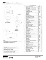
Table 3 

Tube Thread Dimensions (see Figure 7) 

 Male 

Connection

Type

Tube Size

Dimensions:  in (mm) Thread Size* 

and Type 

(in)

OD x ID

in (mm)

D

L

SM250CX20

1/4" x .109

(6.35 x 2.77)

0.141

(3.58)

0.344

(8.74)

1/4" - 28

SM375CX20

3/8" x .203

(9.53 x 5.16)

0.25

(6.35)

0.438

(11.13)

3/8" - 24

SM562CX20

9/16" x .312

(14.29 x 7.92)

0.406

(10.31)

0.500

(12.70)

9/16" - 18

SM562CX10

9/16" x .359

(14.29 x 7.92)

0.438

(11.13)

0.500

(12.70)

9/16" - 18

SM750CX20

3/4" x .438

(14.29 x 9.12)

0.562

(14.27)

0.625

(15.88)

3/4" - 16

SM750CX10

3/4" x .516

(19.05 x 13.11)

0.578

(14.68)

0.625

(15.88)

3/4" - 16

SM1000CX20

1" x .562

(25.4 x 14.27)

0.719

(18.26)

0.781

(19.84)

1" - 14

SM1000CX10

1" x .688

(25.4 x 17.48)

0.812

(20.62)

0.781

(19.84)

1" - 14

SM1500CX

1-1/2" x .937

(38.10 x 23.78)

1.062

(26.97)

1.000

(23.40)

1-1/2" - 12

M250C

1/4" x .083

(6.35 x 2.10)

0.125

(3.18)

0.562

(14.27)

1/4" - 28

M250C100 

(see note)

1/4" x .083

(6.35 x 2.10)

0.125

(3.18)

0.625

(15.88)

1/4" - 28

M312C150

5/16" x .062

(7.94 x 1.57)

0.125

(3.18)

0.687

(17.45)

5/16" - 24

M375C100 

(see note)

3/8" x .125

(9.53 x 3.18)

0.219

(5.56)

0.562

(14.27)

3/8" - 24

M375C

3/8" x .125

(9.53 x 3.18)

0.219

(5.56)

0.75

(19.05)

3/8" - 24

M562C

9/16" x .187

(14.29 x 4.78)

0.281

(7.14)

0.938

(23.83)

9/16" - 18

M562C40

9/16" x .250

(14.29 x 6.35)

0.312

(7.92)

0.938

(23.83)

9/16" - 18

M562C40-312

9/16" x .312

(14.29 x 7.92)

0.406

(10.31)

0.940

(23.88)

9/16" - 18

M10000C43

1" x .438

(25.4 x 11.13)

0.562

(14.27)

0.91

(23.11)

1" - 18

*

 Thread is left-hand national fine (Class 2). All dimensions for reference only 

and subject to change.

Note:

 M250C100 and M375C100 used in F312C150 connection 

at 100,000 psi (6895 bar)

Section 5.0  

Threading Operation

Install Collets and Die Chasers

5.1 

Select the appropriate sized collet and die chasers using 

Table #5 and tube size. Install collets as described in 

Install Collet Section (steps 4.12 through 4.17)

5.2 

Set the locks on the cart’s wheels.

5.3 

Install die chasers in die head.


Note:

 The die head has three positions; closed, open 

and extreme open position.


When the die head is in the closed (cutting) position, the 

die chasers are in position to cut threads.


In the open position, the die chasers are moved away 

from the tubing. This is the position the die head should 

be in when the threading operation is completed and 

when adjusting thread depth.


In the extreme open position, the die chaser slots in the 

die head are exposed permitting the dies to be installed 

or removed.


Note:

 Chasers are ground in matched sets of four (4) and 

available in sets only.

5.3.1 

Trip die head into open position.


With the die head in the closed position, push arms  


mounted on trip yoke toward the motor causing  


head to trip into open position.


5.3.2  

Move die head to extreme open position.


5.3.3  You may have to start and stop the machine    

quickly to get the die head to stop spinning in a good    

position to have access to the head release lever.


Turn the machine off and unplug the power cord.  


Next, press head release lever in (located on adjust- 


ing ring) with an implement, such as a screwdriver,  


to allow the die head to spring back into extreme  


open position (Figure 8). The die chaser slots should  


now be fully exposed with the die head in this position.


5.3.4 

Insert chasers into die head slots.


The chasers and slots are each numbered 1 through  


4. It is critical that the numbered chaser is placed  

into the matching numbered slot. 


For example, No. 1 chaser in No. 1 slot, No. 2 chaser in 

No. 2 slot, etc.

Summary of Contents for AEGCTM-2

Page 1: ...MODELS AEGCTM 2 AEGCTM 2G AEGCTM 2E CE AEGCTM 2E CEG AEGCTM 2WOH AEGCTM 2EWOH CE Coning and Threading Machine Operation and Maintenance Manual Catalog 02 9221ME April 2014 ...

Page 2: ...onnection 10 13 Completed Medium Pressure Connection 11 14 Completed High Pressure Connection 11 15 View of Pump Face 13 16 Pump Reservoir Assembly 13 TABLES 1 Extra Cutting Allowances for Engagement 4 2 Required Feedwheel Rotation for Coning Operation 6 3 Tube Thread Dimensions 7 4 Torque Requirements for Coned Connection 11 5 Tooling Part Number 12 Drawings and Schematics Sheet 1 AEGCTM 2 115 VA...

Page 3: ... covers must be in place at all times and are only to be removed by qualified service personnel with the power cord disconnected 1 6 Operating personnel shall wear eye protection at all times while operating this machine 1 7 When changing tooling or servicing the machine unplug the power cord In the event that either the motor or the pump become stalled unplug the power cord immedi ately to avoid ...

Page 4: ...gure 2 Determine Tube Length Fitting to Fitting Distance Fitting to Fitting Distance 2 x Extra Allowance from Table 1 2 x 1 16 Finish Allowance Cut Length Table 1 Extra Cutting Allowance for Engagement Connection Tubing Size Type OD x ID Engagement Allowances in mm SF250CX 1 4 x 10⁹ 55 14 0 SF375CX 3 8 x 203 69 17 6 SF562CX 9 16 x 312 84 21 3 SF562CX 9 16 x 359 84 21 3 SF750CX 3 4 x 438 1 00 25 4 ...

Page 5: ...collet on a hard surface and place the collet nut over the large end of the collet as shown and push together They should snap together 4 15 To separate a collet from the collet nut grip the collet nut in one hand and pull firmly sideways on the small end of the collet to twist it out of the collet nut 4 16 Install the collet assembly into the holder 4 17 Install the collet and collet nuts for the...

Page 6: ...which is perpendicular to the center line of the tubing The critical finish for coned connections is on the leading edge of the cone The transition point where the cone meets the square end of the tube must be free of burrs and tool marks Figure 7 4 22 Reverse the feedwheel until the tubing is disengaged from the cutting blades Attach the chained hook to the feedwheel and if no one is using the th...

Page 7: ... 0 Threading Operation Install Collets and Die Chasers 5 1 Select the appropriate sized collet and die chasers using Table 5 and tube size Install collets as described in Install Collet Section steps 4 12 through 4 17 5 2 Set the locks on the cart s wheels 5 3 Install die chasers in die head Note The die head has three positions closed open and extreme open position When the die head is in the clo...

Page 8: ...ext to the adjusting ring binding screw and use the tool to rotate the adjusting ring until the desired pitch diameter is obtained The die head adjusting ring is marked with an S smaller pitch diameter and an L larger pitch diameter to indicate the direction to turn the ring to adjust the pitch diameter smaller or larger Figure 9 5 4 4 Tighten adjusting ring binding screw before cutting a thread 5...

Page 9: ...embly against the spacer head which in turn will push against the trip yoke causing it to automatically open the die head and release the tubing 5 10 Turn off the machine and clean the chips out of the die head assembly to prevent damage when the yoke assem bly is pulled away from the die head Pull collet assembly with tube mounted in it away from die head 5 11 Loosen the collet nuts and remove tu...

Page 10: ... and threading Note An optional thermostatically controlled immer sion heater is available for use in cold weather Cutting fluid should be Prestige 1246LV AE Part No P 8699 or equivalent 5 23 To Remove Chasers 5 23 1 Trip die head into open position If the die head is in the closed position push on trip yoke arms toward the motor causing head to trip into open position 5 23 2 Move die head to extr...

Page 11: ...X10 15 16 55 74 6 40 54 4 SF562CX20 15 16 55 74 6 40 54 4 SF750CX10 1 13 16 75 101 6 55 74 6 SF750CX20 1 13 16 90 122 0 70 95 0 SF1000CX10 1 3 8 125 169 5 100 135 6 SF1000CX20 1 3 8 125 169 5 100 135 6 SF1500CX 1 7 8 200 271 2 160 217 0 F250C 5 8 25 33 9 100F250C 5 8 50 67 8 F312C150 3 4 70 94 9 F375C 13 16 50 67 8 100F375C 5 8 105 142 8 F562C 1 3 16 75 101 6 F562C40 1 3 16 60 81 4 SF1000C30 1 3 8...

Page 12: ...chasers Note See the Drawings and Schematic section for information on additional parts not required as spare parts 7 1 Drive Belt for the AEGCTM 2E CE p n P 6958 1 for the AEGCTM 2 p n P 1754 2 7 2 Coning Blade Holder p n 201D 0159 7 3 Coning Threading DVD p n P 9930 D 7 4 Coning Threading Gage 7 5 Other Tooling See Table 5 7 6 Cutting Oil p n P 8699 Section 8 0 Service For service contact the Pa...

Page 13: ...e impeller by hand to make sure it turns freely While keeping the impeller from touching any thing plug the unit in to see if the impeller will turn 6 If it does re install the volute three 3 screws and inlet screen IF FOR ANY REASON THESE OPERATIONS DO NOT RESTORE THE PUMP TO FULL SERVICE CONTACT THE LITTLE GIANT PUMP COMPANY OR IT S AUTHORIZED SERVICE CENTER DO NOT IN ANY CASE OPEN THE SEALED PO...

Page 14: ...14 Parker Autoclave Engineers Instrumentation Products Division Erie PA USA www autoclave com Cat 02 9221ME ...

Page 15: ...15 Parker Autoclave Engineers Instrumentation Products Division Erie PA USA www autoclave com Cat 02 9221ME ...

Page 16: ...16 Parker Autoclave Engineers Instrumentation Products Division Erie PA USA www autoclave com Cat 02 9221ME ...

Page 17: ...17 Parker Autoclave Engineers Instrumentation Products Division Erie PA USA www autoclave com Cat 02 9221ME ...

Page 18: ...18 Parker Autoclave Engineers Instrumentation Products Division Erie PA USA www autoclave com Cat 02 9221ME ...

Page 19: ...19 Parker Autoclave Engineers Instrumentation Products Division Erie PA USA www autoclave com Cat 02 9221ME ...

Page 20: ...toclave com Cat 02 9221ME OIL SPLASH GUARD PARTS LIST KIT PART NUMBER AEGCTM 2GK Item No DESCRIPTION PART NUMBER QTY 1 Oil Guard 90598 1 2 Screw 90596 2 3 Lockwasher Spring 1 4 Regular P 3701 2 4 Bracket Oil Guard 191F 3394 1 5 Screw 90597 2 6 Lockwasher Spring 5 16 Regular P 0841 2 ...

Page 21: ...21 Parker Autoclave Engineers Instrumentation Products Division Erie PA USA www autoclave com Cat 02 9221ME ...

Page 22: ...22 Parker Autoclave Engineers Instrumentation Products Division Erie PA USA www autoclave com Cat 02 9221ME ...

Page 23: ...23 Parker Autoclave Engineers Instrumentation Products Division Erie PA USA www autoclave com Cat 02 9221ME ...

Page 24: ...ible for making the final selection of the system and components and assuring that all performance endurance maintenance safety and warning requirements of the application are met The user must analyze all aspects of the application follow applicable industry standards and follow the information concerning the product in the current product catalog and in any other materials provided from Parker o...

Reviews: