13
Parker Autoclave Engineers
Instrumentation Products Division
Erie, PA USA
www.autoclave.com | Cat. 02-9221ME
4.
Keep the inlet screen and impeller free of debris or
restrictions.
5.
Be sure not to let the unit freeze in the winter as it may
distort or break the pump.
6.
Your unit is lifetime lubricated by the manufacturer.
Lubricating the pump again may damage it and may void
the warranty
7.
Make sure the pump is disconnected from any power
sources before performing any type of service or repair
on the pump.
Pump Service Instructions
Very little service will be required by your pump. If for any rea-
son the unit should fail to operate, follow the suggestions listed
below:
1.
Disconnect pump from electric current. Try it at
another electrical outlet to make sure current is
getting to the unit. If it still does not start:
2.
Remove the intake screen.
3.
Remove three (3) front screws as indicated by the
arrows in Figure 15 and then remove the volute
(cover over the impeller). (Do not remove other
screws which may be exposed.)
Figure 15
View of Pump Face
4.
Lightly clean any corrosion or debris which may
have clogged the volute or impeller. Use a brush and
penetrating oil and lightly scrape away any deposits.
Do not scratch the painted surface.
5.
Turn the impeller by hand to make sure it turns
freely. While keeping the impeller from touching any
thing, plug the unit in to see if the impeller will turn.
6.
If it does, re-install the volute, three (3) screws and
inlet screen.
IF FOR ANY REASON THESE OPERATIONS DO NOT
RESTORE THE PUMP TO FULL SERVICE, CONTACT THE
LITTLE GIANT PUMP COMPANY OR IT’S AUTHORIZED
SERVICE CENTER.
DO NOT, IN ANY CASE, OPEN THE SEALED PORTION OF
THE UNIT OR REMOVE SCREWS OTHER THAN SHOWN
BY ARROWS IN ILLUSTRATION #5.
DO NOT CUT THE ELECTRIC CORD OFF THE PUMP OR
SHORTEN IT WHEN REMOVING THE PUMP. ONLY
DISCONNECT PUMP FROM IT’S ORIGINAL
CONNECTION.
VIOLATIONS OF THESE PROVISIONS OR THOSE
SHOWN IN THE LITTLE GIANT PUMP SERVICE GUIDE
WILL VIOLATE THE WARRANTY ON THE UNIT.
CONDITIONS: This unit is designed to circulate light oils
and other mild liquids. It will operate under more severe
conditions also, but the warranty in such cases will be
subject to approval by the factory.
CONNECT TO SAME SERVICE VOLTAGE AS SHOWN ON
THE PUMP.
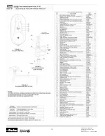
Oil Heater Option
Figure 16
Pump/Reservoir Assembly
For operation below 65ºF (18.3ºC) see page 16.
1.
The heater is used to heat the oil in cold conditions to
help the flow of oil to the cutters and die chasers.
2.
Oil heater is preset at the factory and should not need
adjusting.
3.
Be sure there is sufficent oil in the reservoir before using
the oil heater.
4.
If for any reason the oil heater fails to operate properly
contact the factory for inspections.


