English
5/6
PSH120-630
6 Maintenance
a) Th
e machine is designed and built to guarantee continuous opera-
tion; however, the life of its components depends on the maintenance
performed;
b) when requesting assistance or spare parts, identify the machine
(model and serial number) by reading the data plate located on the
unit.
6.1 General instructions
!
Before any maintenance, make sure:
• the pneumatic circuit is no longer pressurized;
• the dryer is disconnected from the main power supply
.
Y
Always use the Manufacturer’s original spare parts: otherwise the
Manufacturer is relieved of all liability regarding machine malfunctio-
ning
Y
In case of refrigerant leakage, contact qualifi ed and authorized per-
sonnel.
Y
Th
e Schrader valve must only be used in case of machine malfun-
ction: otherwise any damage caused by incorrect refrigerant charging
will not be covered by the warranty.
6.2 Refrigerant.
Charging: any damage caused by incorrect refrigerant replacement car-
ried out by unauthorized personnel will not be covered by the warranty.
Z
Y
Th
e equipment contains fl uorinated greenhouse gases.
At normal temperature and pressure, the R407c refrigerant is a co-
lourless gas classifi ed in SAFETY GROUP A1 - EN378 (group 2 fl uid
according to Directive PED 97/23/EC)
GWP (Global Warming Potential) = 1774.
!
In case of refrigerant leakage, ventilate the room.
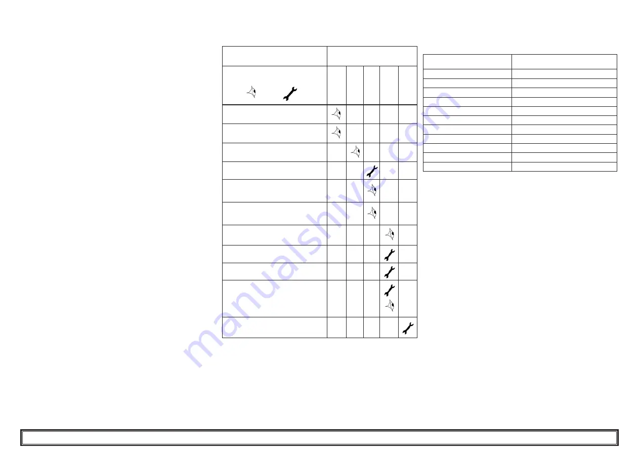
6.3 Preventive Maintenance Programme
To guarantee lasting maximum dryer effi
ciency and reliability
Maintenance
Activity Description
Maintenance Interval
(standard operating conditions
)
Activity
Check
Service
Da
ily
W
eek
ly
4 M
on
ths
12 M
on
ths
36 M
on
ths
Check POWER ON indicator is lit.
Check control panel indicators.
Check condensate drain.
Clean condenser fi ns.
Verify that the crakcase heater is cor-
rectly positioned
Check electrical absorption.
Check refrigerant leaks.
Depressurize the dryer. Complete
drain maintenance.
Depressurize the dryer. Replace pre-
and post-fi lter elements.
Check temperature sensors.
Replace if necessary.
Dryer maintenance kit.
Th
e following are available (see par. 8.4):
a) 3 years preventive maintenance kits;
b) service kit
• compressor kits;
• fan kits;
• hot gas valve kits;
• water condenser kits;
c) individual spare parts.
6.4 Dismantling
Th
e refrigerant and the lubricating oil contained in the circuit must be
recovered in conformity with current local environmental regulations.
%
Recycling Disposal
Z
structural work
steel/epoxy-polyester resins
exchanger
aluminium
pipes/headers
copper/aluminium/carbon steel
drain
polyamide
exchanger insulation
EPS (sintered polystyrene)
pipe insulation
synthetic rubber
compressor
steel/copper/aluminium/oil
condenser
steel/copper/aluminium
refrigerant
R407c
valves
brass
electrical cables
copper/PVC
Summary of Contents for Polestar-HP Smart PSH120
Page 2: ......
Page 28: ...8 5 EXPLODED DRAWING 8 PSH120 630 A B E D C 12 15 B3 4 5 1 8 3 9 2 B1 34 PSH 120 230 Ac ...
Page 29: ...8 5 EXPLODED DRAWING 9 PSH120 630 B A E D C 34 15 12 9 B3 1 2 2 3 8 4 5 B1 4 5 PSH 290 460 Ac ...
Page 31: ...8 6 DIMENSIONAL DRAWING 11 PSH120 630 34 15 9 B3 B E D C A 2 8 1 4 4 5 5 F G 22 B1 PSH 460 Wc ...
Page 33: ...8 6 DIMENSIONAL DRAWING 13 PSH120 630 PSH 120 230 Ac ...
Page 34: ...8 6 DIMENSIONAL DRAWING 14 PSH120 630 PSH 290 460 Ac ...
Page 35: ...8 6 DIMENSIONAL DRAWING 15 PSH120 630 PSH 630 Ac ...
Page 36: ...8 7 REFRIGERANT CIRCUIT 16 PSH120 630 PSH 290 460 Wc ...
Page 37: ...8 7 REFRIGERANT CIRCUIT 17 PSH120 630 PSH 630 Wc ...
Page 38: ...8 7 REFRIGERANT CIRCUIT 18 PSH120 630 PSH 120 230 Ac ...
Page 39: ...8 7 REFRIGERANT CIRCUIT 19 PSH120 630 PSH 290 460 Ac ...
Page 40: ...8 7 REFRIGERANT CIRCUIT 20 PSH120 630 PSH 630 Ac ...
Page 41: ...8 7 REFRIGERANT CIRCUIT 21 PSH120 630 PSH 490 460 Wc ...
Page 42: ...8 7 REFRIGERANT CIRCUIT 22 PSH120 630 PSH 630 Wc ...
Page 43: ...8 8 WIRING DIAGRAM 23 PSH120 630 Sheet 1 of 6 PSH 120 230 Ac ...
Page 44: ...8 8 WIRING DIAGRAM 24 PSH120 630 Sheet 2 of 6 PSH 120 230 Ac ...
Page 45: ...8 8 WIRING DIAGRAM 25 PSH120 630 Sheet 3 of 6 PSH 120 230 Ac ...
Page 46: ...8 8 WIRING DIAGRAM 26 PSH120 630 Sheet 4 of 6 PSH 120 230 Ac ...
Page 47: ...8 8 WIRING DIAGRAM 27 PSH120 630 Sheet 5 of 6 PSH 120 230 Ac ...
Page 48: ...8 8 WIRING DIAGRAM 28 PSH120 630 Sheet 6 of 6 PSH 120 230 Ac ...
Page 49: ...8 8 WIRING DIAGRAM 29 PSH120 630 Sheet 1 of 6 PSH 290 630 Ac ...
Page 50: ...8 8 WIRING DIAGRAM 30 PSH120 630 Sheet 2 of 6 PSH 290 630 Ac ...
Page 51: ...8 8 WIRING DIAGRAM 31 PSH120 630 Sheet 3 of 6 PSH 290 630 Ac ...
Page 52: ...8 8 WIRING DIAGRAM 32 PSH120 630 Sheet 4 of 6 PSH 290 630 Ac ...
Page 53: ...8 8 WIRING DIAGRAM 33 PSH120 630 Sheet 5 of 6 PSH 290 630 Ac ...
Page 54: ...8 8 WIRING DIAGRAM 34 PSH120 630 Sheet 6 of 6 PSH 290 630 Ac ...
Page 55: ...8 8 WIRING DIAGRAM 35 PSH120 630 Sheet 1 of 6 PSH 290 630 Wc ...
Page 56: ...8 8 WIRING DIAGRAM 36 PSH120 630 Sheet 2 of 6 PSH 290 630 Wc ...
Page 57: ...8 8 WIRING DIAGRAM 37 PSH120 630 Sheet 3 of 6 PSH 290 630 Wc ...
Page 58: ...8 8 WIRING DIAGRAM 38 PSH120 630 Sheet 4 of 6 PSH 290 630 Wc ...
Page 59: ...8 8 WIRING DIAGRAM 39 PSH120 630 Sheet 5 of 6 PSH 290 630 Wc ...
Page 60: ...8 8 WIRING DIAGRAM 40 PSH120 630 Sheet 6 of 6 PSH 290 630 Wc ...


