Parallel Galleon Installation Manual Download Page 15

After initialization UPS will enter to No Output mode, then Press and hold the “ON” button for 0.5s to turn 
on the UPS, and the buzzer will beep once. A few seconds later, the UPS will be turned on and enter to 
Battery mode. 

III) Then do the same  procedure to  the other UPS according  II), the  LCD will  display the parallel 

process as showed in the below picture, the sign in the red circle will twinkle until the UPSs entering to the 
battery mode: 


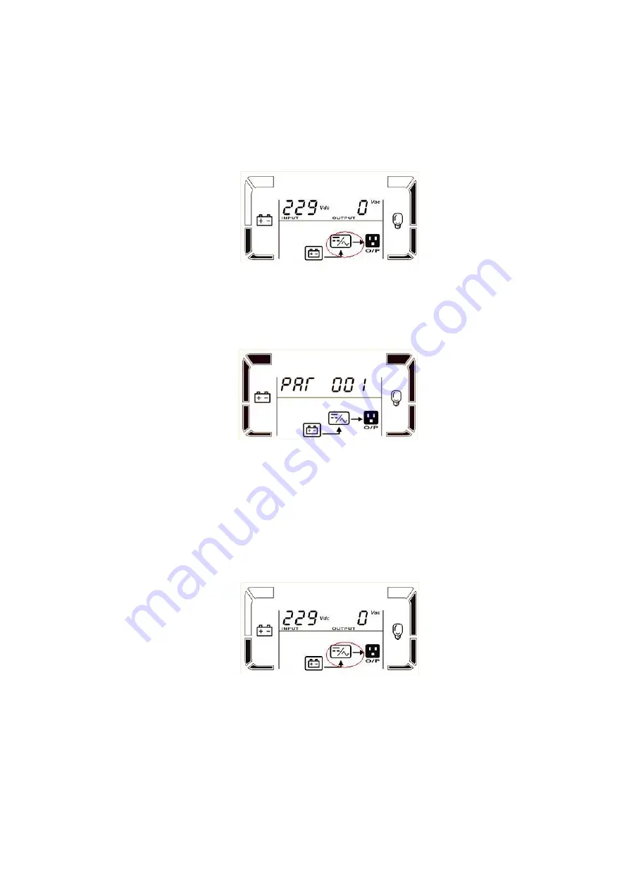
IV) Check the LCD whether displays the parallel information as showed in the below picture. If parallel 

UPS systems are successfully set up, it will show “

PAR

” and assigned number as below picture. The master 

UPS will be default assigned as “

001

” and slave UPSs will be assigned as either “

002

” or “

003

”. If not see 

this picture, you can not go to next step and please check if the parallel cables have been connected well. 


V) Press “OFF” button for 0.5s of each UPS one by one to turn off all UPSs in parallel system. 

b)


Turn on the battery breaker (only for long-run model) and output breaker of each UPS. 

c)


Press the “ON” button of one UPS to set up the power supply, UPS will enter to power on mode. After 
initialization UPS will enter to No Output mode, then Press and hold the “ON” button for 0.5s to turn 
on the UPS, and the buzzer will beep once. 

d)


A few seconds later, the UPS will be turned on and enter to Battery mode. 

e)


Then do the same procedure to the other UPS according c), the LCD will display the parallel process as 
showed in the  below picture, the sign in the red circle will  twinkle until the UPSs entering to the 
battery mode: 


f)


Then the parallel system has been installed and starts to supply power to the load. 

7)


Turn off the parallel system 

Press and hold the “OFF” button for 0.5s to turn off the UPS one by one, the buzzer will beep once. 

After a while, the UPSs will enter to bypass mode or no output mode synchronously. 

8)


Add one new unit into the parallel system 

a)


You can not add one new unit into the parallel system when whole system is running. You must cut off 
the load and shutdown the system. 

b)


Make sure all of the UPSs are the parallel models, and follow the connection refer to section 3. 

Summary of Contents for Galleon

Page 1: ...llowing picture is just for reference 2 Installation Warning For standard model Make sure the UPS is not turned on before installation The UPS should not be turned on during installation Cut off all t...

Page 2: ...ifferent between these two boards the part number The beginning 10 number of the series number and firmware label Label on the MCU in the picture just for reference different version UPS may have diff...

Page 3: ...control board demount the small PCBA board Demount the 3 white screws disconnect the 50 pin cable Replace the PFC control board with a new one It is better assemble the small PCBA first then assemble...

Page 4: ...unt the screw Then pull the INV control board Flipping over the INV control board you can see the glue on the connectors remove the glue then dis connect all the cables Replace the INV control board w...

Page 5: ...the cables on the communication board and demount the srews that used to fasten the communication board to the rear panel Replace the board with a new one connect the cables install the screws 2 3 Par...

Page 6: ...nect CN001 to CN15 of INV1 2 board Connect CN002 to CN16 of INV1 2 board Connect CN003 to CN15 of INV3 board Step 5 Connect the wires that demounted from the OP EMI board by step2 Connect R1 to P1 of...

Page 7: ...upply cable to CN9 of parallel board Connect the S phase current equalizer cable to CN10 of parallel board Connect the T phase current equalizer cable to CN11 of parallel board Step 8 Remove covers fo...

Page 8: ...rt red black cable to CN10 of communication board Step 11 Connect the S phase current equalizer cable the longer red black cable to CN20 of INV 1 2 board Step 12 Connect the T phase current equalizer...

Page 9: ...board Connect the 14 pin grey cable to CN11 of INV control board Step 14 Assemble the INV control board back to INV1 2 board and then make the 14 PIN grey cable through the middle iron board Step 15 C...

Page 10: ...Long Backup Unit 3 Wiring Connection for Parallel Operation Please follow the below steps to connect cables and wires for Gallon 3 3 parallel models Step 1 Parallel cable and share current cable conne...

Page 11: ...each UPS to an output breaker 4 Connect all output breakers to a major output breaker Then this major output breaker will directly connect to the loads Step 3 If the UPS is connected to external batt...

Page 12: ...onverter enable or disable f bypass enable or disable g bypass open or forbidden h frequency auto detect enable or disable i inverter short clear enable or disable 3 Turn on the UPS into the line mode...

Page 13: ...ve this setting into EEPROM Output A voltage calibration Interface Setting Parameter 2 it always shows OP V as output voltage Parameter 3 it shows the internal measurement value of the output A voltag...

Page 14: ...arallel system supplies power to the loads via the bypass c Check the LCD whether displays the parallel information as showed in the below picture If parallel UPS systems are successfully set up it wi...

Page 15: ...breaker only for long run model and output breaker of each UPS c Press the ON button of one UPS to set up the power supply UPS will enter to power on mode After initialization UPS will enter to No Out...

Page 16: ...stem All UPS will transfer to bypass mode c Remove all the maintenance bypass covers and set the maintenance switches from UPS to BPS d Turn off all the input breakers and battery breakers in parallel...

Reviews: