Parallax 29157 Manual Download Page 6

Parallax, Inc.  •  BASIC Stamp HomeWork Board ver 1.1 

Page 6 

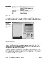
With the SLEEP example the Power LED turns off when the SLEEP command is being executed because the 
EEPROM is inactive. Current consumption is 10 mA while the loop is being executed but drops to 40 µA during 
the SLEEP command. 


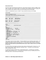
' POWER DEMO - SLEEP.BS2 
' Demonstrating the power LED with SLEEP command STeve 
' {$STAMP BS2} 
 
' I/Os, Constants and Variable definitions 
loopCounter VAR 

Byte 


' Main Program 
Start: 
  FOR loopCounter = 0 to 99 
    DEBUG Home, "loopCounter =", dec loopCounter 
  NEXT 
  SLEEP 1 


GOTO Start 


Precautions 

 
Be alert to static sensitive devices and static-prone situations. The BASIC Stamp, like other integrated circuits, 
can be damaged by static discharge that commonly occurs touching grounded surfaces or other conductors. 
Environmental conditions (humidity changes, wind, static prone surfaces, etc) play a major role in the presence of 
random static charges. It is always recommended to use grounding straps and anti-static or static dissipative 
mats when handling devices like the BASIC Stamp. Since you don’t have a dissipative mat, touch a grounded 
surface after you have approached your work area. This isn’t as critical as you might think but being prudent only 
protects your hardware. 
 
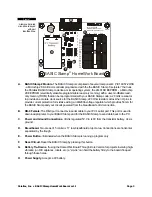
Before building circuits, disconnect the battery.  


Summary of Contents for 29157

Page 1: ...an t have their own Board of Education BS2 due to it s higher cost Since it s less expensive than the Board of Education BS2 module can the board be used for Stamps in Class experiments Possibly with...

Page 2: ...cations are shown below Table 1 Also review the hardware Figure 1 and schematic Figure 2 Table 1 BASIC Stamp HomeWork Board Specifications Microcontroller PIC16C57 surface mount Speed 20 MHz 4 000 ins...

Page 3: ...BASIC Stamp 220 Ohm resistors across the I O pins to provide current protection for mistake wiring an LM2936 voltage regulator which provides 50 mA for the BASIC Stamp and your circuits powered from...

Page 4: ...N2 22 0 RN5 22 0 RN4 22 0 RN3 22 0 Power Consumption and Battery Life Parallax normally designs BASIC Stamp boards with power jacks for wall transformers Wall transformers provide plenty of power but...

Page 5: ...almost two years if you wake the BASIC Stamp once in a while In reality projects need to wake up and provide current to loads like LEDs and other chips used in your project If you know the current dra...

Page 6: ...ecautions Be alert to static sensitive devices and static prone situations The BASIC Stamp like other integrated circuits can be damaged by static discharge that commonly occurs touching grounded surf...

Page 7: ...9V battery and the serial cable to your StampLab Alkaline Battery Powercell Reset 916 624 8333 www parallaxinc com www stampsinclass com Rev A STAMPS CLASS in 2002 Power X3 Vdd Vss Vin P15 P14 P13 P1...

Page 8: ...Parallax Inc BASIC Stamp HomeWork Board ver 1 1 Page 8 Figure 4 Software install Step 1 just click Next Figure 5 Software install Step 2 Choose Typical for a standard installation...

Page 9: ...and modify up to 16 different source code files at once Each source code file that is loaded into the editor will have its own tab at the top of the page labeled with the name of the file Source code...

Page 10: ...e BASIC Stamp Windows Editor any time a source code file is loaded tokenized downloaded run In order to test communication between the BASIC Stamp and your PC download a simple program as shown below...

Page 11: ...Editor supports several shortcut keys that will speed your use of file management editing and coding Tables 3 to 5 Table 3 File Functions shortcut keys Shortcut Key Function Ctrl O Open a souce code...

Page 12: ...eft side and RAM usage right side BASIC and Parallax BASIC BASIC standing for Beginner s All Purpose Symbolic Instruction Code was written invented in 1963 at Dartmouth College by mathematicians John...

Page 13: ...ontrol For our first experiment we ll need just an LED and a 220 ohm Red Red Brown resistor Connect the 220 ohm resistor between pin P15 and the breadboard Connect the LED between the same section of...

Page 14: ...am LED Blink BS2 Purpose Blinks an LED connected to BASIC Stamp pin P15 Start HIGH 15 turn LED on PAUSE 500 wait one half second LOW 15 turn LED off PAUSE 500 wait one half second GOTO Start do it aga...

Page 15: ...constant we now have more of an idea of what is being controlled HIGH 15 could be controlling anything a light a bell a heater We re forced to explain the process of our program in comments By using t...

Page 16: ...Dir15 corresponds to bit 15 of the Dirs register The advantage of going to this depth is that we can gain more flexibility and control over our programs especially in terms of readability this aspect...

Page 17: ...CR DEBUG CR DEBUG Blink Value BIN8 blinkVal CR DEBUG Blink Bit REP 7 blinkBit control the LED LedPin blinkVal LowBit blinkBit PAUSE 5 NEXT NEXT GOTO Start In this program we ll need a couple variable...

Page 18: ...o this line will print seven spaces then the pointer When blinkBit is one it will print six spaces then the pointer You get the idea Now that we know what s going on let s make it happen The line of c...

Reviews: