Parallax 29157 Manual Download Page 15

Parallax, Inc.  •  BASIC Stamp HomeWork Board ver 1.1 

Page 15 

 
Next, we make the LED control pin go to zero volts with 

LOW

.  With zero volts on both sides of the LED, no 

current can flow and it turns off.  Again, we use 

PAUSE

 to create a delay so that we can actually see that it is off.  

Finally, we start the process over by jumping to the line labeled 

Start

 with the 

GOTO

 command.   

 
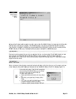
Download and run the program – you should see the LED blink happily on and off.  If you don't, double-check 
your connections; especially the orientation of the LED.  If it doesn't blink you may have it in backward. 
 
Now, as exciting as that was, we can do more and write "better" code.  Better code is code that not only works, 
but is easy for us and others to understand.  Let's improve our  little program just a bit.  Take a look at Listing 1b. 
 

' {$STAMP BS2} 
 
' Program: LED Blink.BS2 (Version B) 
' Purpose: Blinks an LED connected to the BASIC Stamp 
 
' --------------------------------------------------------------- 
 
LedPin          CON     15              ' LED control pin 
 
' --------------------------------------------------------------- 
 
Start: 
  HIGH LedPin                           ' turn LED on 
  PAUSE 500                             ' wait one-half second 
  LOW LedPin                            ' turn LED off 
  PAUSE 500                             ' wait one-half second 
  GOTO Start                            ' do it again 

 
In this version we introduce constant (

CON

) values.  Constants give us a way to assign a useful name to a value 

that doesn't change.  There a couple of good reasons for using constants in our program:  
 

1.  If we need to change the pin that controls the LED, we only have to change one place in the program.  

Using constants prevents program errors by not catching all the changes required when circuit 
connections are modified. 
 

2.  By using a constant, we now have more of an idea of what is being controlled.  

HIGH 15

 could be 

controlling anything; a light, a bell, a heater.  We're forced to explain the process of our program in 
comments.  By using the constant name 

LedPin

, others reading our code know what is being controlled 

and we can spend less energy explaining with comments. 

 
Okay, so I'll bet you're wondering just how constants work..  They're actually used by the editor when the program 
is being compiled to run on the BASIC Stamp.  At the beginning of the compilation process the editor will replace 
all the appearances of a constant name with its defined value.   In our program, 

HIGH LedPin

 will be replaced with 

HIGH 15

 and the program will work just as in our first version.  And don't worry, this replacement is an internal 

process used by the compiler – our source code listing will not be changed. 
 
Give it a try. You'll see that the program runs exactly the same as it did the first time.  This time, though, our listing 
makes a bit more sense.  Ready for more?   
 
One of the things that makes 

HIGH

 and 

LOW

 easy is that each command actually does two operations – that's 

right, two.  You see, to control a Stamp output pin we have to deal with two internal registers.  The first is called 

Dirs

.   The 

Dirs

 register is 16 bits wide; one bit for each I/O pin.  When a bit in the 

Dirs

 register is zero (default at 

start-up), the associated I/O pin will be an input.  When we make a 

Dirs

 bit a one, the associated I/O pin will be an 

output.   
 
The other register that we need to concern ourselves with is called 

Outs

.  Like 

Dirs

Outs

 is 16 bits wide.  In this 

case, the bits in 

Outs

 are connected to the I/O pins when the associated 

Dirs

 bits are set to one.  When a bit in 

Summary of Contents for 29157

Page 1: ...an t have their own Board of Education BS2 due to it s higher cost Since it s less expensive than the Board of Education BS2 module can the board be used for Stamps in Class experiments Possibly with...

Page 2: ...cations are shown below Table 1 Also review the hardware Figure 1 and schematic Figure 2 Table 1 BASIC Stamp HomeWork Board Specifications Microcontroller PIC16C57 surface mount Speed 20 MHz 4 000 ins...

Page 3: ...BASIC Stamp 220 Ohm resistors across the I O pins to provide current protection for mistake wiring an LM2936 voltage regulator which provides 50 mA for the BASIC Stamp and your circuits powered from...

Page 4: ...N2 22 0 RN5 22 0 RN4 22 0 RN3 22 0 Power Consumption and Battery Life Parallax normally designs BASIC Stamp boards with power jacks for wall transformers Wall transformers provide plenty of power but...

Page 5: ...almost two years if you wake the BASIC Stamp once in a while In reality projects need to wake up and provide current to loads like LEDs and other chips used in your project If you know the current dra...

Page 6: ...ecautions Be alert to static sensitive devices and static prone situations The BASIC Stamp like other integrated circuits can be damaged by static discharge that commonly occurs touching grounded surf...

Page 7: ...9V battery and the serial cable to your StampLab Alkaline Battery Powercell Reset 916 624 8333 www parallaxinc com www stampsinclass com Rev A STAMPS CLASS in 2002 Power X3 Vdd Vss Vin P15 P14 P13 P1...

Page 8: ...Parallax Inc BASIC Stamp HomeWork Board ver 1 1 Page 8 Figure 4 Software install Step 1 just click Next Figure 5 Software install Step 2 Choose Typical for a standard installation...

Page 9: ...and modify up to 16 different source code files at once Each source code file that is loaded into the editor will have its own tab at the top of the page labeled with the name of the file Source code...

Page 10: ...e BASIC Stamp Windows Editor any time a source code file is loaded tokenized downloaded run In order to test communication between the BASIC Stamp and your PC download a simple program as shown below...

Page 11: ...Editor supports several shortcut keys that will speed your use of file management editing and coding Tables 3 to 5 Table 3 File Functions shortcut keys Shortcut Key Function Ctrl O Open a souce code...

Page 12: ...eft side and RAM usage right side BASIC and Parallax BASIC BASIC standing for Beginner s All Purpose Symbolic Instruction Code was written invented in 1963 at Dartmouth College by mathematicians John...

Page 13: ...ontrol For our first experiment we ll need just an LED and a 220 ohm Red Red Brown resistor Connect the 220 ohm resistor between pin P15 and the breadboard Connect the LED between the same section of...

Page 14: ...am LED Blink BS2 Purpose Blinks an LED connected to BASIC Stamp pin P15 Start HIGH 15 turn LED on PAUSE 500 wait one half second LOW 15 turn LED off PAUSE 500 wait one half second GOTO Start do it aga...

Page 15: ...constant we now have more of an idea of what is being controlled HIGH 15 could be controlling anything a light a bell a heater We re forced to explain the process of our program in comments By using t...

Page 16: ...Dir15 corresponds to bit 15 of the Dirs register The advantage of going to this depth is that we can gain more flexibility and control over our programs especially in terms of readability this aspect...

Page 17: ...CR DEBUG CR DEBUG Blink Value BIN8 blinkVal CR DEBUG Blink Bit REP 7 blinkBit control the LED LedPin blinkVal LowBit blinkBit PAUSE 5 NEXT NEXT GOTO Start In this program we ll need a couple variable...

Page 18: ...o this line will print seven spaces then the pointer When blinkBit is one it will print six spaces then the pointer You get the idea Now that we know what s going on let s make it happen The line of c...

Reviews: