


9
Connect the Ethernet Line
The 10/100 Ethernet Port auto-negotiates speed and duplex mode in accordance with
the remote equipment to which it is connected; Ethernet speed and duplex mode
configurations cannot be set on the TNE1500. For the best connection results, the
remote device (PC, hub, switch, etc.) should be set to auto-negotiate speed and duplex
mode as well. If the remote device cannot be configured to auto-negotiate, speed may
be set at either 10 Mbps or 100 Mbps but duplex mode must be set to Half Duplex; a
10/100 Ethernet connection will not operate properly if the remote device is set to Full
Duplex.
Plug the Ethernet cable into the 10/100 Ethernet Port on the back of the TNE1500.
Verify the connection: solid green illumination of the 10/100 Ethernet Connection Lnk
(Link) LED on the front of the TNE1500 indicates a connection has been established. If
the Ethernet Lnk LED is illuminated, but not the Ethernet 100 LED, then a 10 Mbps
connection has been established. If the Ethernet Lnk AND 100 LEDs are both
illuminated, then a 100 Mbps connection has been established.
For most applications, the TNE1500 connects to a PC using a straight-through Ethernet
cable and to a hub or a switch using a crossover Ethernet cable. For any other
connection combinations you must verify the pinout of the Ethernet device to which you
are connecting the TNE1500 in order to determine which type of cable is required.
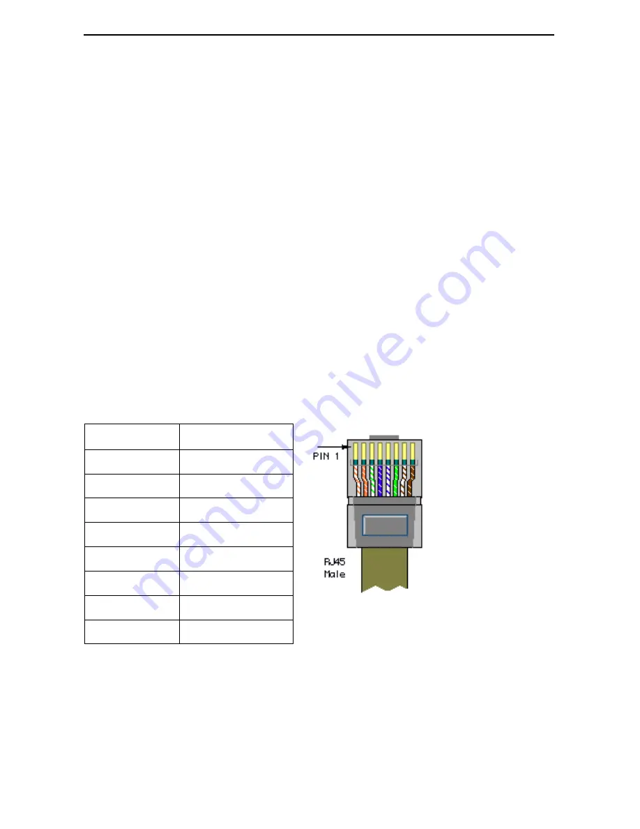
Table 9. Ethernet Pinouts
Pin
Function
Pin 1
Rx+
Pin 2
Rx–
Pin 3
Tx+
Pin 4
not used
Pin 5
not used
Pin 6
Tx–
Pin 7
not used
Pin 8
not used


