15
Optional Hotwire 6301/6302 IDSL Router Wall Placement
The Hotwire 6301/6302 IDSL Router is designed for tabletop placement. The IDSL
router can also be mounted on a wall. To mount the IDSL router, you will need:
-
Three slotted-head #6 self-threading screws with molly bolts
-
Drill and 3/16
″
drill bit for the molly bolts
-
Screwdriver
A template with the dimensions for the three screws is provided. See IDSL Router
Hardware Template on page 16.
"
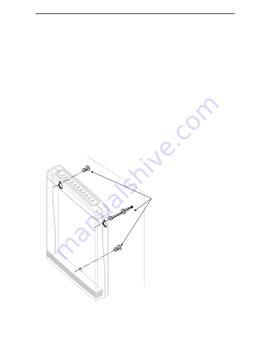
Procedure
To mount the IDSL router:
1. Use a drill to install the plastic anchors (molly bolts).
2. Use a screwdriver to install the screws. Do not install the screws flush with the
wall. Leave enough clearance to hang the IDSL router housing from the screws.
Wall
Fasteners
99-16170-02