Installation and Setup
2-4
5100-A2-GB21-10
April 1997
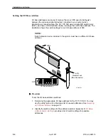
Setting the I/O Base Address
I/O base addresses are areas of memory that your CPU uses to distinguish
between the various peripheral devices connected to your system when
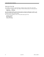
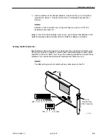
transferring or receiving data. The 5171 PC NIC uses a single DIP switch bank
(SW1), as shown in the illustration below, to assign the card’s base address. The
illustration shows the switch settings for an I/O base address of 380.
NOTE:
Each hardware device included in the system must have a different I/O base
address.
97-14998-01
LEDs
DSL
LNK
CD
RX
TX
TEST
SYS
6-Pin
Modular Jack
(DSL Connector)
1 2
3
4
5
6
7
8
1 2
3
4
5
6
7
8
1 2
3
4
I/O Base Address
6
7
8
ON
1
2
3
4
5
SW1
Procedure
To set the I/O base address switches:
1. Determine the appropriate I/O base address for the 5171 PC NIC. You may
use the utility feature for obtaining a list of unused addresses. See
Selecting
an I/O Base Address
on page 2-3.
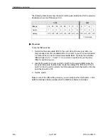
2. Identify the switch settings for the address selected. Appendix D,
I/O Base
Address Switch Settings
, provides a list of switch settings for possible
addresses.

